This effect draws a series of intermeshed gears. It is more of a
toy effect, designed to demonstrate the possibilities of
LPEs. The
Gear
extension can also be used to draw gears with a bit
more control.
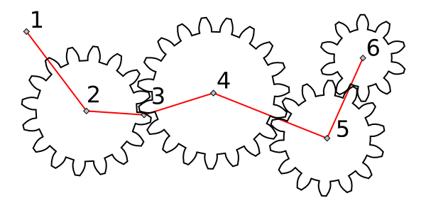
The effect uses the nodes of a path to determine how the gears are
drawn. At least three nodes are needed to specify the first
gear. Additional gears require one additional node each. Some
nodes may be skipped if they would result in impractical gears.
Two parameters are available: Teeth determines
the number of teeth on the first gear. Phi determines
the Pressure Angle of the gears. For real gears the
Pressure Angle is typically 14.5, 20, or 25 degrees.
Note: The default angle is 5 degrees, not a very realistic value.