| Inkscape » Extensions » Generate from Path |    |
|---|
| Inkscape » Extensions » Generate from Path | |
|---|
This group of extensions creates new objects from one or more existing paths.
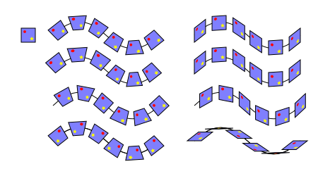
Connects nodes in two paths with lines or with polygons. In the case of lines, it simply draws a line between each corresponding node in the two paths (i.e., a line between the first node of one path and the first node of the other path, etc.). If one path has more nodes than the other, the extra nodes are not used. All the lines are sub-paths of one path. In the case of polygons, a quadrilateral is drawn between corresponding adjacent pairs of points on the two lines. Each quadrilateral is a separate path. All the created paths are placed in a Group. In both cases, the original paths are not changed.
See the Motion for a similar effect utilizing only a single path.

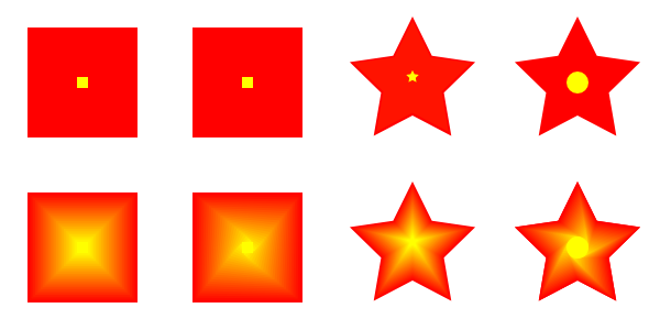
This extension produces a blurred image of the selected object(s). It works by making multiple copies of the object(s) and insetting or offsetting the path of each copy by a different small amount. The opacity of each copy is set to a small value based on the number of copies made. The copies are embedded in a group that is left above the original object(s).
Why would you want to use this extension when Inkscape now supports filters? Well, filter support in web browsers is still in its infancy. Your SVG drawings are more likely to be properly rendered using this extension. The look of the blur is also a bit different.
This extension only works on paths! Convert regular shapes and text to paths before
using ( →
![]() Object to Path
(
Shift+Ctrl+C
)).
Object to Path
(
Shift+Ctrl+C
)).

Draws a series of lines that interpolate the space between two paths. The options include setting the number of Interpolation Steps (in-between lines), an Exponent factor that controls the spacing between interpolated paths (zero for even spacing), specifying if the original paths should be duplicated (Duplicate Endpaths), and specifying that the path style should also be interpolated. Objects need to be converted to paths prior to invoking the extension.

The beginning of the path of one object is matched to the beginning of the other path. This can lead to unexpected effects. The starting point of a path can be found by selecting the path with the Node Tool and then using the Tab key. If no node is already selected, the first node in the path will be selected.

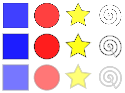
The interpolation extension can also be used to simulate gradients of different symmetries. When calling the extension, the smaller path should be selected first.
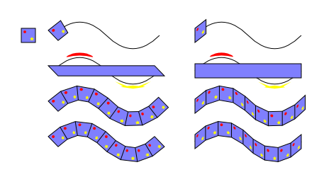
Simulates motion. Draws a copy of the selected object behind the original and then connects corresponding nodes with lines to form a group of closed paths. The direction and offset of the copied object can be specified. The new objects inherit the attributes of the original but can be edited as a group.

One can also use this extension to simulate perspective by reducing the size of the copy along with the associated nodes. The steps are:

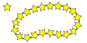
This extension places a pattern along one or more target paths. The pattern can be a single object or a Group of objects. See also Chapter 8, Live Path Effects (LPEs) for an alternative way of putting patterns along paths.
To put a pattern on a path:
Select the pattern: The pattern can be a single object or a Group. In some cases, you may have better results if you explicitly convert all objects (e.g., Shapes) in the pattern to paths.
Select the target path or paths: Called the Skeleton path by the extension author.
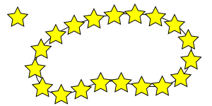
Call the extension: A dialog will open up where various parameters can be selected. After the extension is applied there will be a new path for each object in the pattern. For example, the stars on the line in the above figure are formed by one path.
The bounding box of the pattern is used for placing the pattern along the path, with the bounding box of one pattern copy touching the bounding box of the next copy (if no additional spacing is specified).
When the extension is called up, the following dialog is shown:
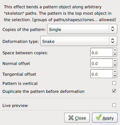
This dialog has many options that can be set (see figures that follow for examples of use):
Copies of the pattern: You can choose to have a Single copy of the pattern placed on the path or multiple copies Repeated along the path. The pattern can be stretched so that the left edge of the first pattern copy lines up with the start of the Skeleton path and the right edge of the last pattern copy lines up with the end of the Skeleton path.
Deformation type: Two options are available:
Snake: The pattern is rotated and deformed to follow the path such that all points with the same horizontal (x) position in the pattern will be on the same normal (perpendicular line) to the path, and all points with the same vertical (y) position in the pattern will be placed the same distance from the path. If the Pattern is vertical box is checked, then the pattern is rotated 90 degrees first.
Ribbon: The pattern is deformed only in either the vertical or horizontal direction to conform to the path. The direction of the deformation is controlled by the Pattern is vertical check box described below.
Space between copies: You can add (or subtract) space between copies of the pattern. The unit is pixel.
Normal offset: The normal offset moves the pattern perpendicular relative to the path. Positive values move the pattern to the left relative to the direction of the path.
Tangential offset: The tangential offset moves the pattern in the direction of the tangent line to the path.
Pattern is vertical: Checking this box rotates the orientation of the pattern by 90 degrees.
Duplicate the pattern before deformation: With this box checked, the original pattern is left in place. Otherwise, it disappears.
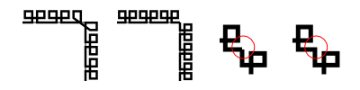
The Pattern along Path is a very useful extension but it does have a few quirks. One is that if the pattern is moved before use, the results may be less than ideal. Another is that different parts of the pattern can be distorted in different ways as seen in figures that follow.

The following example shows a pattern placed on both straight and curved paths. If the radius of curvature is too small, the pattern may be grossly distorted.

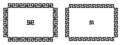
A pattern can be used to create a fancy border as shown
below. Care must be taken that the pattern lines up at the
corners. This can be done by making the distance between the
corner nodes
multiples of the pattern width or by breaking the path into
disconnected pieces at the corners (use the Break Path
at Selected Nodes (
![]() ) option in the
Node Tool Tool Controls) and using the Repeated,
stretched option.
) option in the
Node Tool Tool Controls) and using the Repeated,
stretched option.
Going one step further, a pattern can be applied to a circle. In the following figure, the pattern on the right was applied to a circle (of larger diameter than the solid yellow circle). The resulting path was filled with a radial gradient.

One use of the Single, stretched option is
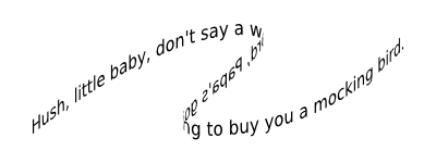
to put text on a path. The text must be converted to a path first
( →
![]() Object to Path
(
Shift+Ctrl+C
)).
Object to Path
(
Shift+Ctrl+C
)).
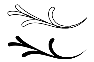
Another use of the Single, stretched option is to create flourishes. (As of v0.47, this is better done by applying the “teardrop” as a custom shape with the Bezier Tool. One would not need to add the extra nodes.) The steps are:

This extension places a pattern along one or more target paths. It is almost identical to the Pattern along Path extension except that the pattern is not deformed.
Most of the options are the same as for the Pattern along Path extension. Those that are different are:
Follow path orientation: The pattern is rotated and to follow the path such that all points with the same horizontal (x) position in the pattern will be on the same normal to the path, and all points with the same vertical (y) position in the pattern will be placed the same distance from the path. If the Pattern is vertical box is checked, then the pattern is rotated 90 degrees first.
Stretch spaces to fit skeleton length: Space is added between pattern copies so they fill evenly the skeleton path.
Original pattern will be: Moved: Original pattern is copied, then deleted. Copied: Original pattern is copied and remains in place. Cloned: Original pattern is cloned, If the original pattern is modified, all patterns along the path will also be modified.
New in v0.48.
Draws Voronoi diagrams. The line segments are derived by distributing sites (points) semi-randomly in an area and then constructing line segments where each point on the segment is equal distance to the two closest sites forming cells around each site.
To use this extension, select a path or object and then call up the extension. There are two settings:
Average size of cell (px): The average cell size (height and width).
Size of Border (px): A positive number greater than the Average size of cell results in a pattern that can be tiled smoothly. A negative number removes sites near the edge resulting in larger cells near the border.
After applying this extension, you will have a Pattern that is applied to the Fill of the object that was selected. The Pattern can be shifted, scaled, and rotated like any other Pattern. It can also be applied to other objects through the Fill tab of the Fill and Stroke dialog.
![[Warning]](../images/admons/warning.png) | Warning |
|---|---|
|
This extension creates a large object that may overtax your computer. |


| |  | |
| Color |  | Images |
© 2005-2017 Tavmjong Bah. |  |