| Inkscape » Quick Start » A Box for Cards—An Isometric Projection |    |
|---|
| Inkscape » Quick Start » A Box for Cards—An Isometric Projection | |
|---|
Inkscape is a two-dimensional drawing program. It can, however, be used to create simple three-dimensional drawings. We will create in this tutorial a simple Isometric Projection.

An isometric projection is a view of an object such that there is an equal opening angle between the three projected orthogonal axes, as shown below.

Inkscape includes axonometric Grids that can be used to rapidly draw isometrically projected boxes. However, the method described here works best when drawings are included on the sides of the boxes as distorting the sides requires two precise transformations (scaling and skewing).
The steps are:
Start Inkscape and set the drawing size.
Create the three sides of the box, unfolded.
Add designs to box sides.
Transform each box side into place.
Procedure 1.5. Creating an Isometric Projection
Set up the drawing.
To begin, start Inkscape.
Follow the instructions for setting the page size and defining a Grid
given in the Swedish flag example but set drawing size to a width
of 500 pixels and a height of 500 pixels. Set the
Grid spacing to 10 pixels.
In the Snap Bar,
enable overall snapping (first
![]() ),
enable snapping to the Grid (
),
enable snapping to the Grid (
![]() ),
enable snapping of the Rotation center (fourth
),
enable snapping of the Rotation center (fourth
![]() , tool tip:
Snap other points; and
, tool tip:
Snap other points; and
![]() ),
and turn off snapping of bounding boxes
(second
),
and turn off snapping of bounding boxes
(second
![]() , tool tip: Snap bounding boxes).
, tool tip: Snap bounding boxes).
Create the three sides of the box.
We need the front, side, and top of the box in the ratio 6:4:1, similar to the dimensions for a deck of cards. Create one rectangle with a width of 200 pixels and height of 300 pixels with the lower edge 100 pixels from the bottom of the page. Create a rectangle to the right of the first with width of 50 pixels and height of 300. Create another rectangle above the first rectangle with width of 200 pixels and a height of 50 pixels. The paths of the rectangles should overlap.
Turn on the Fill of the rectangles with the Palette or Fill and Stroke
dialog ( →
![]() Fill and Stroke...
(
Shift+Ctrl+F
)) and set
the Fill to white. Turn on the Stroke and set the Stroke color to
black and the width to one pixel. Set the Stroke
Join to Bevel by
clicking on the
Fill and Stroke...
(
Shift+Ctrl+F
)) and set
the Fill to white. Turn on the Stroke and set the Stroke color to
black and the width to one pixel. Set the Stroke
Join to Bevel by
clicking on the
![]() icon under the Stroke
style tab in the Fill and Stroke dialog.
This will make the corners where the rectangles touch neater.
icon under the Stroke
style tab in the Fill and Stroke dialog.
This will make the corners where the rectangles touch neater.

Add designs to the box sides.
You can add any designs you want to the box sides. I will use the NP logo created in the previous tutorial as well as some text.
Import the logo using the
→
![]() Import...
(
Ctrl+I
)
command. The logo will need to be scaled smaller. You can do
this by click-dragging on one of its corners. Hold the
Ctrl key down to keep the height to width ratio
constant. Once you have it sized appropriately, you can center
the logo within the large rectangle by using the
→
Import...
(
Ctrl+I
)
command. The logo will need to be scaled smaller. You can do
this by click-dragging on one of its corners. Hold the
Ctrl key down to keep the height to width ratio
constant. Once you have it sized appropriately, you can center
the logo within the large rectangle by using the
→
![]() Align and Distribute...
(
Shift+Ctrl+A
)
dialog. To add the large rectangle to the logo selection, click on
it while holding down the Shift key.
In the Align and Distribute dialog, select
from the Relative to drop-down menu
Last selected. Since the rectangle was
the last object selected, it will remain fixed and the logo will
move. Click on the Center on vertical axis
icon (
Align and Distribute...
(
Shift+Ctrl+A
)
dialog. To add the large rectangle to the logo selection, click on
it while holding down the Shift key.
In the Align and Distribute dialog, select
from the Relative to drop-down menu
Last selected. Since the rectangle was
the last object selected, it will remain fixed and the logo will
move. Click on the Center on vertical axis
icon (
![]() ) and the Center on horizontal axis
icon (
) and the Center on horizontal axis
icon (
![]() ).
).
Add some text to the sides as you wish. When finished, group each
box side with the objects on that side by first selecting the box
side with all the objects inside and the using the
→
![]() Group
(
Ctrl+G
) command. When objects are placed in a Group,
they can be manipulated as if they are just one object. This will
ensure that when the box sides are transformed, the logo and text
will be transformed as well.
Group
(
Ctrl+G
) command. When objects are placed in a Group,
they can be manipulated as if they are just one object. This will
ensure that when the box sides are transformed, the logo and text
will be transformed as well.

Transform each box side into place.
Now the fun begins. We would like to distort each box side into a rhombus with the edges keeping the same length. This cannot be done directly. The distortions require several steps. The steps are to make the box sides narrower and then to skew them. The box top will also have to be rotated.
When the sides are narrowed, we will want to keep the stroke width
from narrowing at the same time. The option to scale stroke width
when an object is scaled can be toggled on and off in the
Tool Controls when the Select Tool is in use. Make sure the
Scale Stroke Width
![]() icon
is not highlighted (or if the icon is not shown because the window
is too narrow, that the Scale stroke width box
is not checked). If it is, toggle off the
option.
icon
is not highlighted (or if the icon is not shown because the window
is too narrow, that the Scale stroke width box
is not checked). If it is, toggle off the
option.
Select the box front (largest side). We want to be precise when we
narrow the sides so we'll use the →
![]() Transform...
(
Shift+Ctrl+M
)
dialog. Bring up the dialog and select the
Scale tab. Set the Width
box to 86.603%. This is equal to cos(30°).
Click on the
Apply button. Use the
Select Tool to drag the box front back
against the other lower box side. It should snap into place.
Transform...
(
Shift+Ctrl+M
)
dialog. Bring up the dialog and select the
Scale tab. Set the Width
box to 86.603%. This is equal to cos(30°).
Click on the
Apply button. Use the
Select Tool to drag the box front back
against the other lower box side. It should snap into place.
Next we need to skew the box front by 30°. This is easiest done with the Select Tool. Click on the box front a second time to change the scaling handles into rotating and skewing handles. When you do so, a small cross, the Rotation center, should appear in the center of the selection. This is the reference point for rotation or skewing. Click-drag this cross to the upper-right corner of the box front. Be careful that it doesn't snap to the corner of the bounding box. The cross should be centered in the middle of the Stroke. If it isn't, it will lead to small alignment problems at end. You can zoom in to check.
Now click-drag the scaling handle (double headed vertical arrow) on the left side of the box front upward while holding down the Ctrl key. Using the Ctrl key will snap the skewing to multiples of 15°. Drag until the skew is −30° (watch the Notification Region).
Repeat the last steps with the box side on the lower right, just interchanging “left” and “right.”
The box top also needs to be narrowed by the same amount as the others, but this time in the vertical direction. Set the Width back to its default value and the Height to 86.603% before scaling the rectangle. Before skewing, move the Rotation center to the lower right corner of the box top. Again make sure the cross is in the middle of the stroke width, aligned with the grid. Skew the rectangle 30° by dragging the top skewing handle right while using the Ctrl key. Finally, rotate the box top 30° clockwise by dragging the upper-left rotation handle while holding the Ctrl key down.
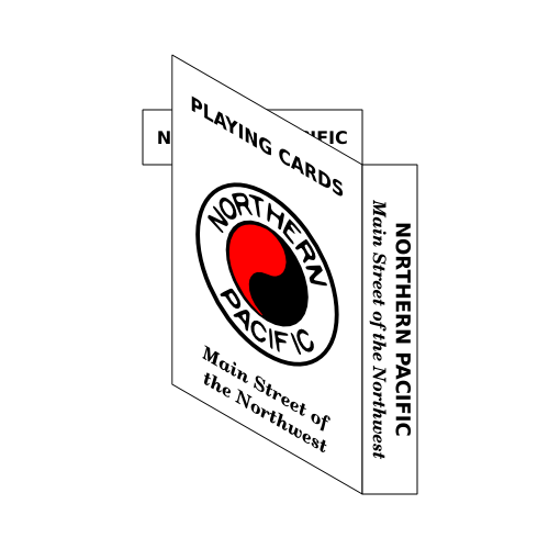
The box of playing cards is now finished. Save your work as in the previous tutorials.
If you did not place the Rotation center exactly as specified (e.g., on the bounding box rather than the middle of the stroke), you may have a small misalignment in the box sides. One can either redo the steps or simply nudge the offending side into place using the Arrow keys while holding the Alt key down.

| |  | |
| The Northern Pacific Railway Logo—A Tracing Example |  | A Can of Soup—A Three-Dimensional Drawing with Gradients |
© 2005-2017 Tavmjong Bah. |  |