| Inkscape » Quick Start » A Can of Soup—A Three-Dimensional Drawing with Gradients |    |
|---|
| Inkscape » Quick Start » A Can of Soup—A Three-Dimensional Drawing with Gradients | |
|---|
We will use Inkscape to draw a soup can. This example will cover: combining and dividing paths, using Gradients, making shadows, and distorting text.

The steps we'll take are:
Start Inkscape, set the drawing size, and specify a grid.
Draw the can shape.
Add a gradient.
Add a shadow.
Add a label background.
Add the label text.
Spiff up the can top.
Procedure 1.6. Drawing a Soup Can
Set the canvas parameters.
Start Inkscape. Set the drawing size to 200 by 200 pixels. Set
up a Grid with spacing of 5 pixels.
Enable overall snapping (first
![]() ),
snapping of nodes
(third
),
snapping of nodes
(third
![]() , tool tip: Snap nodes, paths, and handles),
snapping to smooth nodes (
, tool tip: Snap nodes, paths, and handles),
snapping to smooth nodes (
![]() ),
and snapping to the Grid.
Disable snapping of bounding boxes
(second
),
and snapping to the Grid.
Disable snapping of bounding boxes
(second
![]() , tool tip: Snap bounding boxes).
, tool tip: Snap bounding boxes).
Draw the can shape.
The can will be composed of two lines connecting parts of two ellipses. (One could use a rectangle to obtain the straight lines but that has the tendency of producing extra nodes.)
Draw the top of the can.
Click on the Ellipse Tool icon
![]() in the Tool Box on the left of the Inkscape window (or
use one of the keyboard shortcuts:
F5 or
e) to select the
Ellipse Tool.
Draw an ellipse to represent the top of the can by click-dragging
between the 50 and 150 pixel marks on the horizontal axis
and between the 150 and 180 pixel marks on the vertical axis.
Give the ellipse a solid color Fill by clicking on a colored
square in the Palette (I've used light red).
in the Tool Box on the left of the Inkscape window (or
use one of the keyboard shortcuts:
F5 or
e) to select the
Ellipse Tool.
Draw an ellipse to represent the top of the can by click-dragging
between the 50 and 150 pixel marks on the horizontal axis
and between the 150 and 180 pixel marks on the vertical axis.
Give the ellipse a solid color Fill by clicking on a colored
square in the Palette (I've used light red).
Draw the bottom of the can.
Duplicate the ellipse by selecting the ellipse (if not selected) and
clicking on the
![]() icon in the Command Bar
or using the menu entry
→
icon in the Command Bar
or using the menu entry
→
![]() Duplicate
(
Ctrl+D
).
A copy of the ellipse will be placed on top of the original ellipse.
The new ellipse will be left selected.
Duplicate
(
Ctrl+D
).
A copy of the ellipse will be placed on top of the original ellipse.
The new ellipse will be left selected.
Move the ellipse down by click-dragging it while holding down the Ctrl key to constrain the movement to the vertical direction. Move it down until the top is at the 50 pixel mark on the vertical axis. You now have the top and bottom of the can.

Draw the side of the can.
The side of the can will be formed by joining the bottom half of the top ellipse to the bottom half of the bottom ellipse. In the process, we will sacrifice both ellipses. Because we still need a separate top for the can as it will be colored differently from the body, we'll duplicate the top ellipse and sacrifice the new copy.
Select the top ellipse and duplicate it as above. Then with the
duplicate ellipse still selected, convert the ellipse into a path
object by using the
→
![]() Object to Path
(
Shift+Ctrl+C
)
command. The object will not appear to have changed but the underlying description
is now an editable path.
Object to Path
(
Shift+Ctrl+C
)
command. The object will not appear to have changed but the underlying description
is now an editable path.
To edit the path, select the Node Tool by clicking on the
![]() icon
(F2
or n)
in the Tool Box.
Select the top node of the path and delete it by clicking on the
icon
(F2
or n)
in the Tool Box.
Select the top node of the path and delete it by clicking on the
![]() icon (Delete selected nodes) in the
Tool Controls or by using one of the keyboard shortcuts:
Backspace or Delete.
icon (Delete selected nodes) in the
Tool Controls or by using one of the keyboard shortcuts:
Backspace or Delete.
Open the path up by selecting the two side nodes and clicking on the
![]() (Delete segment between two non-endpoint nodes) icon
in the Tool Controls.
(Delete segment between two non-endpoint nodes) icon
in the Tool Controls.
Repeat the previous steps for the bottom ellipse (except for duplicating it). You should have a drawing that looks like the following one if you change the color of the still intact top ellipse:

Next the top and bottom half ellipses need to be joined together. Select
both and combine into one path with the
→
![]() Combine
(
Ctrl+K
)
command.
Combine
(
Ctrl+K
)
command.
With the Node Tool, select the two leftmost nodes, one from
the top and one from the bottom. Join them by clicking on the
![]() (Join selected endnodes with a new segment) icon in the
Tool Controls.
Repeat for the two rightmost nodes.
(Join selected endnodes with a new segment) icon in the
Tool Controls.
Repeat for the two rightmost nodes.
You should now have a well-constructed can side, as shown below.

Add a gradient for a 3D effect.
A Gradient can represent the reflections off the curved part of
the can. There are two ways to add a gradient, the first is to use
the Gradient Tool and the second to use the Fill and Stroke
dialog.
To add a Gradient using the Gradient Tool, select the
tool by clicking on the
![]() icon
(Ctrl+F1 or g) in the Tool Box.
Then with the can side selected, click-drag from the left side of
the can to the right side.
To add a Gradient using the Fill and Stroke dialog, open
the dialog ( →
icon
(Ctrl+F1 or g) in the Tool Box.
Then with the can side selected, click-drag from the left side of
the can to the right side.
To add a Gradient using the Fill and Stroke dialog, open
the dialog ( →
![]() Fill and Stroke...
(
Shift+Ctrl+F
)). Select the
Fill tab, if not already selected, and with
the can side selected, click on the Linear
gradient (
Fill and Stroke...
(
Shift+Ctrl+F
)). Select the
Fill tab, if not already selected, and with
the can side selected, click on the Linear
gradient (
![]() ) icon.
Both methods create a default Gradient across the can side using
the preexisting Fill color.
) icon.
Both methods create a default Gradient across the can side using
the preexisting Fill color.
The Gradient needs a bit of work to make it look proper which is easiest done with the Gradient Tool. Two Gradient handles will appear when the can side is selected.

Gradients are defined in terms of Stops. A Stop has a color and position (offset) in the Gradient. The default Gradient has two Stops, both with the same color but with different transparencies. For the side of the can, we'll use three Stops.
Add a third Stop by double-clicking on the line connecting the two existing Stops with the Gradient Tool enabled and the can side selected. The cursor will have an extra + sign when it is possible to add Stops. When you add a Stop it takes on the color of the Gradient at the place where it is added. The look of the Gradient will not change.
The Stop (handle) can be dragged to move it. Move it to the center.
Now let's give our can a shiny metallic look. Select the leftmost Stop by clicking once on it. Change the color to dark gray by either clicking on the 80% Gray swatch in the Palette (a tool tip with the color name will be displayed when the cursor is over a swatch) or by using the Fill and Stroke dialog. Both the Fill and Stroke paint tabs will show the color of the Stop and can be used to change the color. With the RGB tab; change the values to R: 51, G: 51, B: 51, A: 255.
Select the middle Stop and set its color to White with the Palette or R: 255, G: 255, B: 255, A: 255 with the Fill and Stroke dialog. Finally, select the last Stop and set its color to match the first Stop. You should now have a metallic can with a highlight that is in the center.

Let's move the highlight to the side. One way to do this would be to further edit the Gradient, changing the position of the middle Stop and maybe lightening or darkening the side Stops. However, the easier way is to move the Gradient handles.

Before we continue, let's make a couple of quick cosmetic changes: Turn off the Stroke of both the can side and top (click on x at left end of Palette while holding down the Shift key). Change the color of the top to 40% Gray (R: 153, G: 153, B: 153).

Our can has a light shining on it from the right but no corresponding shadow. We'll fix that now. To do it perfectly is not an easy feat. Inkscape is a 2D drawing program and cannot project shadows for 3D objects (try POV-Ray for that). But we can do a pretty good approximation.
Create the shadow object.
For the shadow, we need to combine copies of the top and of the side of the can into one object. We'll play a similar game to that used to create the side of the can.
Select the top of the can (an ellipse) and duplicate it. Change its color to make
it easier to keep track of. Any color will do. Convert the new ellipse
to a path
( →
![]() Object to Path
(
Shift+Ctrl+C
)).
Remove the bottom node
(change to the Node Tool,
Object to Path
(
Shift+Ctrl+C
)).
Remove the bottom node
(change to the Node Tool,
![]() ).
Select the two side nodes and remove the line in between them
(
).
Select the two side nodes and remove the line in between them
(
![]() ).
).
Select the side of the can, duplicate it, and change its color. Remove the top three nodes. Select the remaining two side nodes and remove the line in between them.

Select both new objects. Combine them into one path
( →
![]() Combine
(
Ctrl+K
)).
Select the two nodes on the left side, join them
(
Combine
(
Ctrl+K
)).
Select the two nodes on the left side, join them
(
![]() ),
and convert the path in between to a line
(
),
and convert the path in between to a line
(
![]() ).
Do the same for the two right nodes.
).
Do the same for the two right nodes.
Distort the shadow shape.
Select the three top nodes and move them down and over, as shown below.

It is clear that the side nodes are not properly positioned and
the path is distorted. We'll make a few adjustments to set this straight. But
first put the shadow object behind the can
( →
![]() Lower to Bottom
(
End
)).
Lower to Bottom
(
End
)).
Node handles are used
to control the direction and curvature of a path on either side
of a node. The handles are the circles attached by straight
lines to a node that are displayed when the node is
selected. The lines are always tangent to the path at the point
the path intersects the node. The distance between the handle
and its node controls the curvature of the path—the farther
away, the less curved is the path near the node. If no node
handles are visible, make them visible by clicking on the
![]() icon in the Tool Controls
or if the icon is not visible, check the Show
handles box in the drop-down menu opened by
clicking on the down arrow at the right end of the
Tool Controls.
icon in the Tool Controls
or if the icon is not visible, check the Show
handles box in the drop-down menu opened by
clicking on the down arrow at the right end of the
Tool Controls.
The nodes indicated by the arrows in the following figure need to be adjusted. The handle on the leftmost node needs to be rotated a small amount counterclockwise so that the handle line is parallel to the side of the shadow. This produces a smooth transition between the straight side and the curved part of the shadow. To make the rotation, drag the handle while holding down the Alt key (which keeps the distance between the handle and node constant).
The other node indicated by the arrow also needs to have its handle adjusted in the same way. In addition, the node should be moved slightly down to the right so that the shadow's straight edge is tangent to the can's bottom.

Now change the color of the fill to 50% Gray (R: 127 G: 127 B: 127).
Soften the shadow's edge.
The easiest way to soften the shadow's edge is to use the Blur slider on the Fill tab of the Fill and Stroke dialog. A value of 3% gives a nice shadow.
Select the new blurred shadow.
Move the shadow to the back
( →
![]() Lower to Bottom
(
End
)).
Lower to Bottom
(
End
)).
One problem needs to be taken care of. The shadow leaks out from the bottom of the can in the front. Select the shadow and move it slightly up and to the left. You can do this either by dragging the shadow with the mouse or using the Arrow keys. Holding down the Alt key while using the Arrow keys will allow finer adjustments.

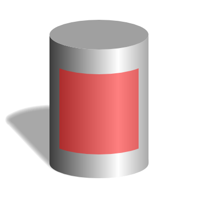
Add a label.
The label has the same curvature as the side of the can. To make the label, we'll take a slice from the can side and then decrease its height.
Select the side of the can and duplicate it. Then select the Rectangle Tool and draw a rectangle that extends from above the can to below the can and extends from 60 to 140 pixels in the horizontal direction.
Select both the new rectangle and the duplicate of the can side.
Use the
→
![]() Intersection
(
Ctrl+*
)
command to form the label from the intersection of the two selected objects.
Intersection
(
Ctrl+*
)
command to form the label from the intersection of the two selected objects.
Change the Fill of the label to a solid red by clicking the
red square in the Palette or by first clicking on the
Flat color (
![]() ) icon in
the Fill tab of the Fill and Stroke dialog
and then changing the sliders to red (R: 255: G: 0: B: 0).
Change the opacity to 50% using the 0: entry
box in the Style Indicator (at the lower-left corner of the
Inkscape window) or using the Opacity
slider in the Fill and Stroke dialog. This will allow a bit of
the can highlight to leak through. (If you desire a metallic
label, just change the color of the gradient.)
) icon in
the Fill tab of the Fill and Stroke dialog
and then changing the sliders to red (R: 255: G: 0: B: 0).
Change the opacity to 50% using the 0: entry
box in the Style Indicator (at the lower-left corner of the
Inkscape window) or using the Opacity
slider in the Fill and Stroke dialog. This will allow a bit of
the can highlight to leak through. (If you desire a metallic
label, just change the color of the gradient.)
With the Node Tool, select the three nodes along the top of the label at the same time and move them down 25 pixels. Move the bottom three nodes of the label up 25 pixels.
Add text to the label.
To add text to the label, select the Text Tool. Click somewhere
on the canvas and type in the text “SPLIT PEA SOUP” with a
carriage return after each word. To change the size and style of
the text, use the drop-down menus in the Tool Controls.
Pick an appropriate font (I've used Bitstream Vera Sans) and font
size (18 pt or 24 px).
The line spacing may need to be adjusted using the
line-spacing entry box
(
![]() ). Change the line spacing to 1 without
any unit in the neighboring unit drop-down menu.
Finally, change the text to a nice Split Pea green with
the Fill and Stroke dialog (R: 63, G: 127: B: 0).
). Change the line spacing to 1 without
any unit in the neighboring unit drop-down menu.
Finally, change the text to a nice Split Pea green with
the Fill and Stroke dialog (R: 63, G: 127: B: 0).
Now, align the text to the center of the can. First
click on the
![]() icon in the
Tool Controls to use the center of the text for snapping.
Then in the Snap Bar enable snapping of text with the
Snap other points (fourth
icon in the
Tool Controls to use the center of the text for snapping.
Then in the Snap Bar enable snapping of text with the
Snap other points (fourth
![]() )
and the Snap anchors and baselines
(
)
and the Snap anchors and baselines
(
![]() ) icons as well as the
Snap to grid (
) icons as well as the
Snap to grid (
![]() )
icon. Finally, drag the text until it snaps to the center-most
grid line.
)
icon. Finally, drag the text until it snaps to the center-most
grid line.

Now we have flat text on a round can! Inkscape can shift and
rotate individual letters of text but it cannot skew the text as
is needed for the characters toward the edge of the can. In order
to skew the letters, we will convert the text into a path and
modify the path. To do this, select the text and then use the
→
![]() Object to Path
(
Shift+Ctrl+C
) command. The text has become a Group
of path objects and can no longer be edited as text. It will be
easier to modify the paths if they form just one path.
Ungroup the objects using →
Object to Path
(
Shift+Ctrl+C
) command. The text has become a Group
of path objects and can no longer be edited as text. It will be
easier to modify the paths if they form just one path.
Ungroup the objects using →
![]() Ungroup
(
Shift+Ctrl+G
) and then
combine the individual letters into one path using
→
Ungroup
(
Shift+Ctrl+G
) and then
combine the individual letters into one path using
→
![]() Combine
(
Ctrl+K
).
Combine
(
Ctrl+K
).
We'll use a couple of very handy Extensions to do the hard work for us.
Start by using the Add Nodes extension to increase the number of nodes in the path. This will improve the look of the final letters. Select the text path, then select → → . A small dialog will pop up, allowing you to set the upper limit to the space between nodes. Set the Maximum segment length to 5.0 and click the Apply button.
Next we'll use the Pattern along
Path extension to put the text on a path. There is
a →
![]() Put on Path command, but this uses the SVG
textPath specification, which would result in
the letters being rotated to follow the path.
Put on Path command, but this uses the SVG
textPath specification, which would result in
the letters being rotated to follow the path.
We need a path to put the text on. The path should be an arc with
the same shape as the curve of the top ellipse but have the width
of the text. Select the top Ellipse of the top of the can and
duplicate it ( →
![]() Duplicate
(
Ctrl+D
)). Move the Ellipse
straight down to the center of the can. Remove the Fill but add
a Stroke. Add a Rectangle that overlaps the bottom of the
Ellipse, centered on the can and with the width of the text.
Duplicate
(
Ctrl+D
)). Move the Ellipse
straight down to the center of the can. Remove the Fill but add
a Stroke. Add a Rectangle that overlaps the bottom of the
Ellipse, centered on the can and with the width of the text.

The Rectangle should be on top of the Ellipse. Select both and
use the →
![]() Cut Path
(
Ctrl+Alt+/
) command to divide the Ellipse
into two pieces. The Rectangle will disappear. Use the
Node Tool to select the top piece of the Ellipse and then
delete it ( →
Cut Path
(
Ctrl+Alt+/
) command to divide the Ellipse
into two pieces. The Rectangle will disappear. Use the
Node Tool to select the top piece of the Ellipse and then
delete it ( →
![]() Delete
(
Delete
or
Backspace
)).
Delete
(
Delete
or
Backspace
)).
The extension requires that the Pattern
(text in this case) be above the path in z-order (that is, on top
of the path). You can move the pattern to the top by selecting it
and then clicking on the Raise to Top
( →
![]() Raise to Top
(
Home
)) icon.
Raise to Top
(
Home
)) icon.
Next, select the text and the path.
Call up the
Pattern Along
Path extension
( → → ). This will open
a dialog. In the dialog, select Single in the
Copies of the pattern menu and
Ribbon in the Deformation
type menu. All the entry boxes should be 0.0 and none
of the boxes should be checked. Click the
Apply button. The text might be
backward. In that case, flip it with the →
![]() Flip Horizontal
(
H
)
command. Finally, delete the small arc.
Flip Horizontal
(
H
)
command. Finally, delete the small arc.

Spiff up the can top.
There is no stopping at the level of detail you can add. In the final figure, a series of ovals of different sizes, positions, and gradients have been used to give the top of the can more realism. These ovals are shown in an expanded view in the next figure.

All the ellipses were created by taking the original can top, duplicating it, and then using the Scale tab of the Transform dialog. The fill was then changed to either a flat fill or a linear gradient with the same colors as used for the rest of the can.
| |  | |
| A Box for Cards—An Isometric Projection |  | A Vine Design—A Tiling Example |
© 2005-2017 Tavmjong Bah. |  |