Part 1 introduced SVG filter primitives and demonstrated the creation of a Fabric filter effect. Part 2 shows various ways to colorize the fabric. It ends with an example of using the techniques learned here to draw part of a bag of coffee beans.
Dying the Fabric
Our fabric at this point is white. We can give it color a variety of ways. We could have started off with a colorized pattern but that would not allow us to change the color so easily. And as this is a tutorial on using filters, lets look at ways the color can be changed utilizing filter primitives.
Coloring with the Flood, Blend, and Composite Primitives
We can use the Flood filter primitive to create a sheet of solid color and then use the Blend filter primitive to combine it with the fabric. The resulting image bleeds into the background. We’ll use the Composite filter primitive to auto-clip the background.
The Flood Filter Primitive
Add the Flood filter primitive to the filter chain by selecting Flood and clicking on the Add Effect button. The fabric will turn a solid black. Like the Turbulence filter primitive, the Flood filter primitive takes no inputs but simply fills the filter region with a solid color Black is the default flood color. You can change the color by clicking on the color sample next to Flood Color: in the dialog. Change the color however you wish. Leave the Opacity at one.
The Blend Filter Primitive.
Next add the Blend filter primitive. The drawing will be unchanged. Connect the Blend input to the last Displacement Map. The fabric should appear on top of the flood fill. This is expected as the default blending mode is Normal which simply draws the second image over the first. Use the drop-down menu to change the Mode to Multiply. This results in the lighter areas of the fabric taking on the flood color.

The output of the filter chain after blending.
Try experimenting with the other blending modes.
The Composite Filter Primitive
The flood fill leaks into the background. This can be removed by clipping the image to fabric area using the Composite filter primitive. Add the Composite filter primitive to the filter chain. The resulting image is again unchanged. Connect the second input to the composite filter to the last Displacement Map filter primitive. Still the image remains unchanged. Now change the Operator type to In. This dictates that the image should be clipped to the area that is “In” the image created by the second Displacement Map filter primitive.

The Filter Effect dialog after adding and adjusting the Flood, Blend, and Composite filter primitives.

The output of the filter after compositing.
Coloring the Fabric with the Component Transfer Filter Primitive
The Component Transfer filter primitive maps, pixel by pixel, the colors from an input image to different colors in an output image. Each “component” (Red, Green, Blue, and Alpha) is mapped independently. The method for mapping is determined by the Type; each Type has its own attributes. We’ll use the Linear and Identity mappings.
- Identity
- The output component has the same value as the input component.
- Linear
- The output component is equal to: intercept + input × slope. This is identical to the Identity type if the intercept is zero and the slope is one.
Replace the Flood Fill, Blend, and Composite filter primitives in the above filter chain by the Composite Transfer filter primitive. (To delete a filter primitive, right-click on the filter primitive name and select Delete in the menu that appears.) The just removed three-primitive filter chain mapped black to black and white to the flood color. We can duplicate this by setting the Red, Green, and Blue component transfer types to Linear (keeping the Alpha component type set to Identity). The condition that black maps to black requires that the Intercept values all be set to zero. The condition that white maps to the flood color dictates the slopes. The RGB values for the flood color used above are 205, 185, 107 on a scale where 255 is the maximum value. These values translate to 0.80, 0.73, 0.42 on a scale where the maximum value is one. Since an input value of 1.0 for the red component must result in a value of 0.80 we can see that these values are the required slopes.

Graph of the transfer functions.

The Filter Effect dialog after adding and adjusting the Component Transfer filter primitive.
The output of the filter after adding and adjusting the Component Transfer filter primitive.
Now suppose we want the fabric to be more subtle. We can change the mapping so that for each component, zero is mapped to half the maximum value. In this case we have the following values (RGB): Intercepts: 0.40, 0.36, 0.21 and Slopes: 0.40, 0.37, 0.21. See the following figure:

Graph of the transfer functions where the darkest value is half the lightest value.

The Filter Effect dialog after adding and adjusting the Component Transfer filter primitive.
The output of the filter after adjusting the Component Transfer filter primitive so the darkest areas have half the component values of the lightest.
Coloring the Fabric with the Color Matrix Filter Primitive
This filter primitive, unlike the Component Transfer, can intermix the color components. It does not, however, have the fine control over the transfer curves like in the Component Transfer filter primitive. There are several Types in this filter primitive. The Saturate, Hue Rotate, and Luminous to Alpha types are shortcuts for the more generic Matrix type. We need to use the Matrix type to match the results of the previous filters.
First replace the Component Transfer filter primitive by the Color Matrix filter primitive. After adding the new primitive, the fabric may disappear; that is a bug in Inkscape. Click on the matrix in the Filter Dialog and the fabric should reappear. The initial matrix is the Identity matrix (consisting of ones on the diagonal) which does not change the image.
The rows in the matrix control the output of, from top to bottom, the Red, Green, Blue, and Alpha channels. The columns correspond to the input, again in the same Red, Green, Blue, and Alpha order. The last column allows one to enter a constant offset for the row. For example, one can make a green object red by changing the top row to “0 1 0 0 0″ which means that the Red channel output is 0×R + 1×G + 0×B + 0×A + 0, where R, G, B, and A are the input values for the Red, Green, Blue, and Alpha channels respectively (on a scale of zero to one).
To change the values in the matrix, click first on a row of numbers to select the row and then click on a numeric entry in the row. The following figures show the values needed to match the fabric samples above.

The Filter Effect dialog after adding and adjusting the Color Matrix filter primitive to match the first (high contrast) fabric sample above.

The Filter Effect dialog after adding and adjusting the Color Matrix filter primitive to match the second (lower contrast) fabric sample above.
Coloring the Fabric Using the Fill Color and the Tile Filter Primitive
In an ideal world, a fabric filter would just take as input the color of an object and use that to blend with a pattern. SVG filters do have the ability to do this. One would read in a pattern tile using the Image filter primitive and then tile the pattern using the Tile filter primitive. But the Tile filter primitive is the one filter primitive that Inkscape hasn’t implemented. While more convenient, this method would still lack the fine control over color that the above methods have.

The output of a filter using the Tile primitive. The two rectangles differ only in Fill color. Renders correctly in Chrome, incorrectly in Firefox and Inkscape.
Putting it All Together
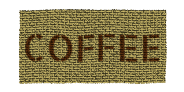
Let’s do something with the fabric! We could stencil some text on the fabric to make it look like part of a bag of coffee beans. The best way to do this is to break the filter up into two separate filters. The first will distort the weave (using the first Turbulence and Displacement Map pair and color the fabric while the second will add a gentle wave to both the fabric and text (using the second Turbulence and Displacement Map pair). The text is given its own filter to take away the sharp edges and to also give it a bit of irregularity independent of the weave. The text could be blended on top of the fabric by giving it an opacity of less than one. A better effect can be achieved, however, by using the new mix-blend-mode property. Inkscape can render this property but does not yet have a GUI to set it. Firefox supports this property and Chrome should soon (if it doesn’t already). I’ve used the mix-blend-mode value of multiply by adding the property to the text style attribute with the XML editor. The fabric and text are then grouped together before applying the “wave” filter to the group.

Part of a bag of coffee beans. Three filters are used. The first to distort the weave and give color to the fabric, the second to slightly blur and distort the text, and the third to take the blended together fabric and text and give them both a gentle wave.
Note, it is possible to put the text in the “defs” section and use the Image filter primitive to import the text into a filter so that the blending can be done with the Blend filter primitive. This isn’t easy to do in Inkscape and Firefox seems to have problems rendering it.
I hope you enjoyed this tutorial. Please leave comments and questions!
A PNG image just for Google+ which doesn’t support SVG images.