CSS Text Line Spacing Exposed!

Want evenly spaced lines of text like when writing on the lined paper we all used as kids? Should be easy. Turns out with CSS it is not. This post will show why. It is the result of too much time reading specs and making tests as I worked on Inkscape’s multi-line text.

The first thing to understand is that CSS text works by filling line boxes with glyphs and then stacking the boxes, much as is done in printing with movable type.

Four lines of movable type placed in a composing stick over a box of movable type.

Movable type placed in a composing stick. The image has been flipped horizontally so the glyphs are legible. (Modified from photo by Willi Heidelbach [CC BY 2.5], via Wikimedia Commons)

A line of CSS text is composed of a series of glyphs. It corresponds to a row of movable type where each glyph represents (mostly) a piece of type. The CSS ‘font-size’ property corresponds to the height of the type. A CSS line box contains a line of CSS text plus any leading (extra space) above and below the line.

Four lines of text mimicking the above figure.

The same four lines of text as in the previous figure. The CSS line boxes are shown by red rectangles. The line boxes are stacked without any leading between the lines.

The lines in the above figure are set tight, without any spacing between the lines. This makes the text hard to read. It is normal in typesetting to add a bit of leading between lines to give the lines a small amount of separation. This can be done with CSS through the ‘line-height’ property. A typical value of the ‘line-height’ property would be ‘1.2’ which means in the simplest terms to make the distance between the baselines of the text be 1.2 times the font size. CSS dictates that the extra space be split, half above the line, half below the line. The following example uses a ‘line-height’ value of 1.5 (to make the figure clearer).

Same four lines of text as in above figure but with leading added between lines.

The same four lines of text as in the previous figure but with leading added by a ‘line-height’ value of 1.5. The distance between the baselines (light-blue lines) is 1.5 times the font size. (Line boxes without leading are shown in green, line boxes with leading in red.)

Unlike with physical type faces, lines can be moved closer together than the height of the glyph boxes by using a ‘line-height’ value less than one. Normally you would not want to do this.

Same four lines of text as in above figure but with negative leading.

The same four lines of text as in the previous figure but with negative leading generated by a ‘line-height’ value of 0.8.

When only one font is used (same family and size), the distance between the baselines is consistent and easy to predict. But with multiple fonts it becomes a bit of a challenge. To understand the inner workings of ‘line-height’ we first need to get back to basics.

Glyphs are designed inside an em box. The ‘font-size’ property scales the em box so when rendered the height of the em box matches the font size. For most scripts, the em box is divided into two parts by a baseline. The ascent measures the distance between the baseline and the top of the box while the descent measures the distance between the baseline and the bottom of the box.

Diagram of 'em' box showing ascent and descent.

The coordinate system for defining glyphs is based on the “em box” (blue square). The origin of the coordinate system for Latin based glyphs is at the baseline on the left side of the box. The baseline divides the em box into two parts.

The distinction between ‘ascent’ and descent’ is important as the height of the CSS line box is calculated by finding independently the maximum ascent and the maximum descent of all the glyphs in a line of text and then adding the two values. The ratio between ascent and descent is a font design issue and will be different for different font families. Mixing font families may then lead to a line box height greater than that for a single font family.

Two 'M' glyphs from different fonts aligned to their alphabetic baseline.

Two ‘M’ glyphs with the same font size but from different font families (DejaVu Sans and Scheherazade). Their glyph boxes (blue rectangles) have the same height (equal to the em box or font size) but the boxes are shifted vertically so that their baselines are aligned. The resulting line box (dashed red rectangle), assuming a ‘line-height’ value of ‘1’, has a height that is greater than if just one font was used.

Keeping the same font family but mixing different sizes can also give results that are a bit unexpected.

Two text blocks.

Left: Text with a font size of 25 pixels and with a ‘line-height’ value of ‘2’. Right: Same as left but font size of 50px for middle line. Notice how the line boxes (red dashed rectangles) are lined up on a grid but that the baselines (light-blue lines) on the right are not; the middle right line’s baseline is off the grid.

So far, we’ve discussed only ‘line-height’ values that are unitless. Both absolute (‘px’, ‘pt’, etc. ) and relative (‘em’, ‘ex’, ‘%’) units are also allowed. The “computed” value of a unitless value is the unitless value while the “computed” value of a value with units is the “absolute” value. The actual value “used” for determining line box height is for a unitless value, the computed value multiplied by the font size, while for the values with units it is the “absolute value” For example, assuming a font size of 24px:

‘line-height:1.5′
computed value: 1.5, used value: 36px;
‘line-height: 36px’
computed and used values: 36px;
‘line-height: 150%’
computed and used values: 36px;
‘line-height: 1.5em’
computed and used values: 36px.

The importance of this is that it is the computed value of ‘line-height’ that is inherited by child elements. This gives different results for values with units compared to those without as seen in the following figure:

Two text blocks.

Left: Text with a font size of 25 pixels and with a ‘line-height’ value of ‘2’. Right: Same as left but ‘line-height’ value of ‘2em’. With the unitless ‘line-height’ value, the child element (second line, span with larger font) inherits the value ‘2’. As the larger font has a size of 50px, the “used” value for ‘line-height’ is 100px (2 times 50px) thus the line box is 100px tall. With the ‘line-height’ value of ‘2em’, the computed value is 50px. This is inherited by the child element which is then used in calculating the line box height. CodePen.

The astute observer will notice that in the above example the line box height of the middle line on the right is not 50 pixels as one might naturally expect. It is actually a bit larger. Why? Recall that the line box height is calculated from the maximum ascent and maximum descent of all the glyphs. One small detail was left out. CSS dictates that an imaginary zero width glyph called the “strut” be included in the calculation. This strut represents a glyph in the containing block’s initial font and with the block’s initial font size and line height. This throws everything out of alignment as shown in the figure below.

'A' and 'D' glyphs aligned to a common baseline with the 'D' having twice the font size as the 'A'.

Let the ‘A’ represents the strut. The glyph boxes for the ‘A’ and ‘D’ without considering line height are shown by blue rectangles. The glyph boxes with line height taken into account are shown by red-dashed rectangles. For the ‘D’, the glyph boxes with and without taking into account the line height are the same. Note that both the ‘A’ and ‘D’ boxes with line height factored in have the same height (2em relative to the containing block font size). The two boxes are aligned using the ‘alphabetic’ baseline. This results in the ‘A’ glyph box (with effect of line height) extending down past the bottom of the ‘D’ glyph box. The resulting line box (solid-pink rectangle) height is thus greater than either of the glyph box heights. The extra height is shown by the light gray rectangle.

So how can one keep line boxes on a regular grid? The solution is to rely on the strut! The way to do this is to make sure that the ascents and descents all child elements are smaller than the containing block strut’s ascent and descent values. One can do this most easily by setting ‘line-height’ to zero in child elements.

Two blocks of text, both showing evenly spaced lines. The third line on the right has text with a font size twice the rest of the lines.

Text with evenly spaced lines. Left: All text with the same font size. Right: The third line has text with double the font size but with a ‘line-height’ value of ‘0’. This ensures that the strut controls the spacing between lines. CodePen.

As one can see, positioning text on a regular grid can be done through a bit of effort. Does it have to be so difficult? There maybe an easier solution on the horizon. The CSS working group is working on a “Line Grid” specification that may make this trivial.
SVG Working Group Editor’s Meeting Report — London — 2016

First, let me thank all the people that donated to Inkscape’s SVG Standards Work fund as well as to the Inkscape general fund that made my attendance possible.

The subset of the SVG working group met in London after the LGM meeting to get down to the nitty gritty of getting the SVG 2 specification ready to move to the “Candidate Recommendation” (CR) stage. Three of the core group members (Nikos, Amelia, and myself) were joined some of the days by three other group members who do not normally participate in the weekly teleconferences. This was a great chance to get some new eyes looking at the spec.

Most of the time was spent in reading the specification together. We managed to get through about half the chapters including the most problematic ones. When we found problems we either made changes on the fly if possible or filed issues if not. We recently switched to Github to keep track of issues which seems to be working well. You can see outstanding issues at our issue tracker. (Feel completely free to add your own comments!)

Minutes of the meetings can be found at:

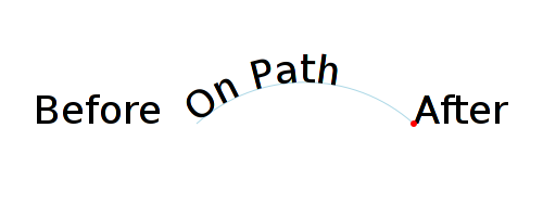
As this was a meeting focused on getting the spec out the door, our discussions were pretty mundane. Nevertheless, let me give you a flavor of the kinds of things we addressed. It was brought up in the issue tracker that the specification is unclear on how text should be rendered if it follows a <textPath> element. It never occurred to me (and probably to most people) that you could have in an SVG file the following:

<text x="50" y="150">Before<textPath xlink:href="#path">On Path</textPath>After</text>
]]>

For an implementer, it is fairly straight forward to figure out where to position the “Before” (use the ‘x’ and ‘y’ attributes) and the “On Path” (use the path) but where should the “After” be rendered? Firefox won’t render it at all. Chrome will render the “After” starting at the end position of the ‘h’ in “On Path”. After some discussion we decided that the only really logical place to render the “After” was at the end of the path. This is the only point that is well defined (the ‘h’ can move around depending on the font used to render the text).

Defining a fill area using <div&gt and floats.

How the above text element is rendered according to the decision of the group at the London meeting. The starting point for text after the <textPath> element is at the end of the path (red dot).

We will have another editor’s meeting in June in Amsterdam where hopefully we’ll finish the editting so we can move the spec to CR. We’ll then need to turn our attention to writing tests. Please consider making a donation to support my travel to this meeting at the link at the start of the post! Thanks.

SVG Working Group Meeting Report — Sydney — 2016

The SVG Working Group had a four day face-to-face meeting in Sydney this month. Like last year, the first day was a joint meeting with the CSS Working Group. I would like to thank all the people that donated to Inkscape’s SVG Standards Work fund as well as to the Inkscape general fund that made my attendance possible.

Joint CSS and SVG Meeting

Minutes

CSS Stroke and Fill Specification

The CSS working group would like to allow the use of the SVG ‘stroke’ and ‘fill’ properties on CSS text as well as other places in CSS (e.g. box border). They’ve created a prototype document that basically copies the SVG stroke and fill text adding the necessary parts to get it to work with CSS text. This document has been temporary called Text Decoration 4 (the title will certainly be changed). They’ve proposed converting the ‘stroke’ and ‘fill’ properties to short-hands. (A short-hand property allows setting multiple CSS properties at the same time.) They also would like to see the ‘stroke-alignment’ property implemented (this property allows one to stroke only the inside or only the outside of a shape). I pointed out the difficulty in actually defining how ‘stroke-alignment’ would work. The SVG WG moved some of the advance stroking properties out of the SVG 2 specification into an SVG Stroke module to avoid holding up the SVG 2 specification. (See my blog entry on this as well as the issues in the SVG Stroke module.) Other issues discussed were how glyphs are painted (‘paint-order’, ‘text-shadow’), multiple strokes/fills, dashing, and ‘text-decoration-fill/stroke’.

Text Issues

Next we covered a whole slew of text issues I raised dealing with flowed text in SVG.

Strategy for using CSS in SVG for wrapping

The first issue was to agree on how SVG and CSS are related. I presented my strategy: that HTML/CSS and SVG have there own methods to define an area to fill called the wrapping area. Once this area is defined, one uses CSS rules to fill it. Here is how one defines the wrapping area in both HTML/CSS and SVG:

The CSS/HTML code:
    <style>
      .wrapper { shape-inside: xxx; ... }
      .float-left { shape-outside: yyy; ... }
      .float-right { shape-outside: zzz; ... }
    </style>
    <div id="wrapper">
      <div id="float-left"/>
      <div id="float-right"/>
      <p>
	Some text.
      </p>
    </div>
The result:
Defining a fill area using <div&gt and floats.

Wrapped text in HTML. One starts with a wrapper <div>. The ‘shape-inside’ property on this <div> reduces the wrapping area to the circle. Two floats <div>s are defined, one on the left (green rectangle) and right (red rectangle). The area that the floats exclude is reduced by the half-ellipses defined by the ‘shape-outside’ property. The final wrapping area is the light blue shape.

The CSS/SVG code:
    <style>
      .my_text { shape-inside: xxx; shape-outside: yyy, zzz; ... }
    </style>
    <text id="my_text">Some text.</text>
The result:
Defining a fill area in SVG.

Wrapped text in SVG 2. One starts with a element. The ‘shape-inside’ property on this element defines the wrapping area. The ‘shape-outside’ property reduces the wrapping area. The final wrapping area is the light blue shape.

It was pointed out at a discussion on Day 2, that the use of ‘shape-outside’ in SVG was not consistent with the CSS model. The ‘shape-outside’ property defines the effective shape of an element as seen by other elements. We agreed to change ‘shape-outside’ to an SVG only property ‘shape-subtract’.

How is the first line placed in a wrapped shape?

When the top of a wrapping area is not horizontal, how do you decide where the first line of text is placed?
Different strategies for locating the position of the first line in pyramid shape.

Alternative solutions for where to start layout of the first line, from top to bottom: First place a chunk of text fits: No restrictions, Restricted to multiples of ‘line-height’, Restricted to multiples of half ‘line-height’.

We were informed that with CSS floats, the line is moved down until the first text chunk fits. To be consistent with CSS, we should follow the same rule. A future CSS Line Grid specification may allow one to control line position.

Overflow text

What should happen when the shape isn’t big enough for all the text? This is mostly an issue for browsers where the user can specify a larger font (i.e. for accessibility reasons). CSS has an ‘overflow’ property that selects either clipping or scrolling. Neither of these is a great solution for SVG. The tentative solution in the CSS Shapes 2 specification of extending the <div> below the wrapping area doesn’t work for SVG. I proposed that there should be a means to expose the overflowed text, such as displaying it on hovering over the ellipses at the end of the displayed text. There was some interest in this. For the moment, the best solution is probably to explicitly not define what should happen, leaving it to a future time to specify the behavior. In reflecting on this after the meeting, I think one strategy is to suggest that authors provide an overflow region by adding an additional shape to the value of the ‘shape-inside’ property.

How does text wrap in a shape with a doughnut hole or other feature that breaks a line into parts?

Since SVG can have arbitrary shapes, it is possible to create shapes that break a single text line into parts. How should these shapes be filled?
A shape a bit like an 'H' showing text be laid out on both sides of the central break.

An example of a shape that breaks lines into parts.

The ‘wrap-flow’ property does not apply here as that dictates how text is flowed around floats. A new ‘wrap-inside’ property has been proposed. For the moment, however, it was agreed that text should flow as shown in the above figure. This would be the default value of any new property.

Flowing into multiple shapes

The aborted SVG 1.2 specification allowed text to be flowed sequentially into multiple shapes. This is something that Inkscape implemented and I would like to see this ability preserved. The proposed CSS methods for doing this don’t work for SVG. I proposed giving the ‘shape-inside’ property a list of shapes. It was agreed that this would be an acceptable solution for SVG. (And it can provide a place for over-flowed text.)

How is the first glyph positioned on a line?

When dealing with rectangles, it is straight forward to find the position of the first glyph but with arbitrary shapes it is more difficult. I asked what was the correct CSS method. I was told that one considers the glyph box extended upwards/downwards as dictated by using the height of the entire line box. (For example, if one has a ‘line-height’ value of 2 with a 16px font, the line box has a height of 32px.) It’s not clear where this is specified in CSS.

Baseline issues

We next switch from text wrapping to baseline issues. Text is normally laid out along a baseline which can be different depending on the script. For example, western scripts normally use an Alphabetic baseline while Indic scripts use a Hanging baseline.
Three different scripts showing their baselines.

Example baselines (red lines) in three different scripts. From left to right: alphabetic, hanging, ideographic. The EM box is shown in blue for the ideographic script.

The proposed CSS definition of the ‘dominant-baseline’ property differs from the SVG 1.1 definition in that several of the SVG 1.1 values are missing. We discussed the missing values. Some of the missing values will be added to the CSS definition. There is one fundamental difference between CSS and SVG 1.1: With SVG 1.1 (and XSL 1.1), the baseline table does not change automatically when the font size is change. One must explicitly reset the table by setting the ‘dominant-baseline’ property to the ‘reset-size’ value. The proposed CSS definition will automatically reset the table on change in font size. I’m not sure this is a necessarily good change (it’s definitely not backwards compatible) but then this is probably such a small corner case that it doesn’t really matter.

Figure from the XSL 1.1 specification showing the default behavior upon ‘font-size’ change. The baseline table does not change.

The CSS ‘auto’ value has one small problem for SVG. With vertical text, if the value of ‘text-orientation’ is ‘sideways’, the alphabetic baseline is used. SVG 1.1 always uses the central baseline for vertical text. The CSS specification will be fixed to be compatible with SVG 1.1.

We also discussed default values for the various baselines. In principle, one gets the values of the baselines from the font but most fonts don’t have baseline tables; for interoperability we need defaults. It was decided that the CSS group would investigate this more and come up with a recommended set of default values.

Filters

I brought up a couple of issues dealing with SVG/CSS Filter Effects module. The first was the status of the document. Progress towards finishing this document seems to have stopped. Two of the three editors are no longer very active. The third editor was present and said he would push this through.

I was also interested in the next level as I have a filter primitive I would like to see added. It turns out that Level 2 has already been started. Not much is in there now. Apple, however, has a bunch of filter primitives they would like to add.

Next we covered the issue of artifacts created by using eight bit per channel colors (8 bpc) in the filter chain. The specification as written doesn’t directly specify that 8 bpc color should be used but a couple examples do assume this. I proposed that they be converted to use the range 0 to 1 so that one can use floats to describe color channels. This would solve the problem. Dean Jackson from Apple will investigate the possibility of requiring that floats be used rather than ints in the filter chain.

A blob showing artifacts due to the use of only an 8 bit bump map as input to a lighting filter primitive.

An example of the artifacts one gets due to using only 8 bit alpha channel bump map as the input into a lighting filter primitive.

Gradient Banding

An unplanned topic… how to get rid of banding in gradients. Dithering is a well known technique. Can dithering be added to CSS gradients? There seems to be support for this idea. The syntax and technique needs to be specified.

SVG Meeting — Day 1

Minutes

Path Stroking: Conformance

I brought up some time ago the inconstancy in how paths are stroked with the half the stroke width is greater than the radius of curvature (see my blog post). I suggested that maybe we define the proper way to stroke a path. Another SVG Working Group member took an action to research this topic more. He consulted members of the PDF standards group as well as hardware vendors. After he presented his findings we agreed that being more specific at this time wasn’t really a viable option as the way paths are stroked is such a fundamental property of the underlying graphics libraries that are used to render SVG.

Fallback for the ‘arc’s Line Join

It has been noted that the currently specified fallback for the ‘arcs’ line join of a ‘miter’ join is less than idea. I presented a number of alternative options to the working group. They agreed to a change in the fallback to one of two possible fallbacks:

Fallback options: Blue: increasing the radius of the inner arc to meet the outer arc. Red: increasing the radius of the inner arc while decreasing the radius of the outer arc until the two meet.

I added to Inkscape trunk’s ‘Join type’ LPE the different possible fallbacks for people to test. A full discussion can be found at here. If you have an opinion, let me know.

Path morphing

With the possible demise of SMIL animations, I asked what was the status of turning the path data attribute into a property so that it can be animated using CSS/Web Animations. The response was that it hasn’t been forgotten and that Chrome will soon have an implementation. (SMIL usage shot up dramatically after YouTube started to use SMIL to animate the Play/Pause button.) CSS path animation will be based on SVG 1.1’s path animation. A future version might include more flexible rules for path interpolation (at the moment, animated paths must have the same number and type of path commands).

SVG Meeting — Day 2

Minutes (Some minutes missing due to operator error…. The meeting crossed midnight GMT which confuses the minute making bot.)

Presentation Attributes

SVG has the idea of presentation attributes. These are attributes that can also be set using CSS. Recently, we’ve promoted quite a few geometric attributes to be presentation attributes to allow setting them with CSS (it does seem a bit strange to “style” the position of a rectangle… but that is what we’ve enabled). As we add new properties, should these also be turned into presentation attributes? It is a bit of a maintenance burden to ensure all new properties are also presentation attributes, especially as we adopt a plethora of new text properties. We have already decided to require CSS so there is not necessarily a need for new presentation attributes. HTML has already deprecated/removed presentation attributes in favor of CSS. After a bit of discussion, we have decided to follow HTML’s lead.

Other Topics

Topics covered included how SVG is integrated into HTML, coordinate precision in generated content, and aligning dashes to corners. As mentioned earlier, we decided to create a ‘shape-subtract’ property rather than misuse the ‘shape-outside’ property. Most of the afternoon was spent with specification editing.

SVG Meeting — Day 3

This was a specification editing day. (It is extremely useful to have the working group present when editing as any issues that arise can be immediately dealt with.)

Font Features Land in Inkscape Trunk

I’ve just landed basic font features support in the development version of Inkscape. What are font features and why should you be excited? (And maybe why should you not be too excited.)
The letter combination 'st' shown without a ligature and with a 'historical' ligature.

Font Features

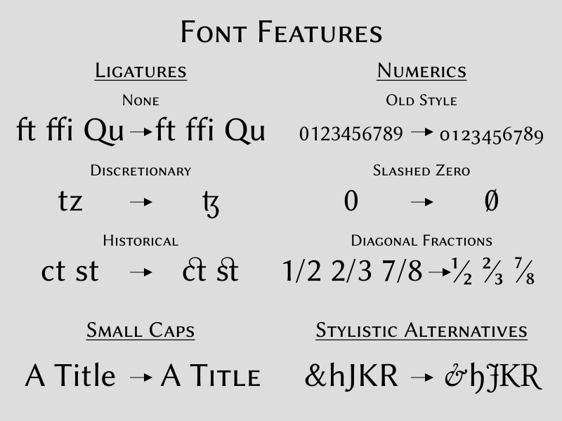
Font features support allows one to enable (or disable) the OpenType tables within a given font, allowing you to select alternative glyphs for rendering text.
A series of examples showing the same text with and without applying various OpenType tables.

A sample of font features in action. The font is Linux Biolinum which has reasonable OpenType tables. Try the SVG (with WOFF).

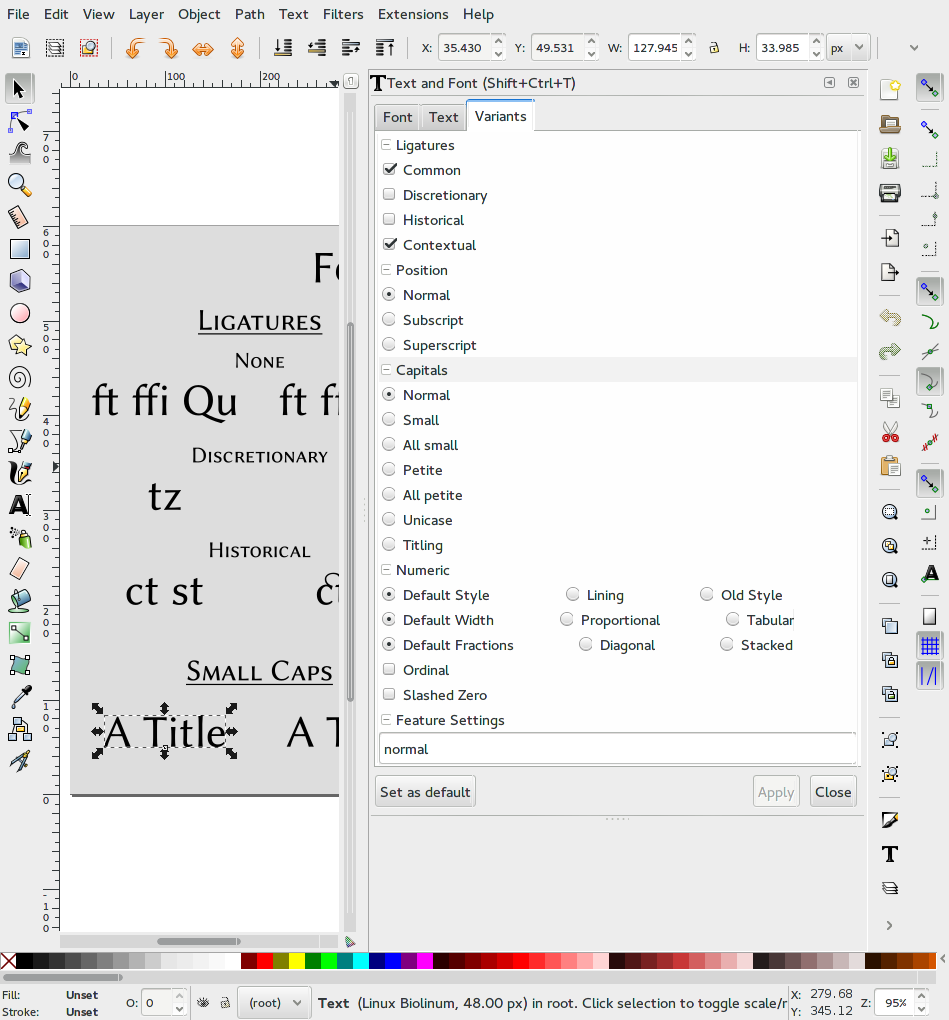
The new CSS Fonts Module Level 3 adds a variety of CSS properties for defining which OpenType tables to enable/disable (as well as having nice examples of each property’s use — this is one of the more readable W3C specifications). Inkscape trunk supports the ‘font-variants-liguatures’, ‘font-variant-caps’, ‘font-variant-numeric’, ‘font-variant-position’, and ‘font-feature-settings’ properties. The properties can be set under the Variants tab in the Text and Font dialog.
The 'Variants' Tab in the 'Text and Fonts' dialog showing a series of buttons to select which font features are enabled.

The Variants tab in the Text and Font dialog.

Why you shouldn’t be too excited

Being able to enable various font features within a font is quite exciting but there are quite a few caveats at the moment:
  • One must use a trunk build of Inkscape linked with the latest unstable version of Pango (1.37.1 or greater).
  • Font feature support in fonts is usually minimal and often buggy. It’s hard to know what OpenType tables are available in which fonts.
  • Browser support is sparse. Firefox has rather good support. Chrome support seems limited to ligatures. UPDATE: As of Chrome 52, Chrome supports font features.
  • Correct display of alternative glyphs requires that the same font as used in content creation is used for rendering. On the Web the best way to do this is to use WOFF but Inkscape has no support for using User fonts (this is a future goal of Inkscape but will require considerable work).

Thanks

I would like to thank: Behdad Esfahbod, maintainer of Pango for adding the code to Pango to make accessing the OpenType tables possible. Thanks as well to Matthias Clasen and Akira Togoh who are the source of the patch to Pango. Thanks also to all the people that supported the Inkscape Hackfest in Toronto where I was able to meet and discuss Pango issues with Behdad in person and also where the idea of adding font feature support to Inkscape germinated.

Paths: Stroking and Offsetting

Path stroking and offsetting are two intertwined topics; stroking is often implemented by path offsetting. This post explores some of the problems encountered with these path operations.

Stroking: It’s not as easy as it looks.

What could be easier that stroking a path? It’s a fundamental concept in all graphics libraries. You construct a path: in PostScript:
newpath
100 100 moveto
150 100 lineto
10 setlinewidth
stroke
in SVG:
<path d="M 100,100 150,100" stroke-width="10"/>
and voila, you have a horizontal path, 50 pixels long, that is 10 pixels wide. Hmm, if only it were that easy. It turns out that stroking an arbitrary path can be quite complicated. Different graphics libraries can give quite different results.
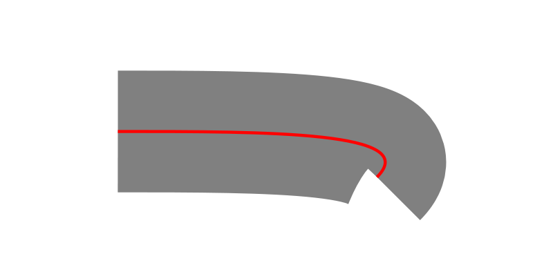
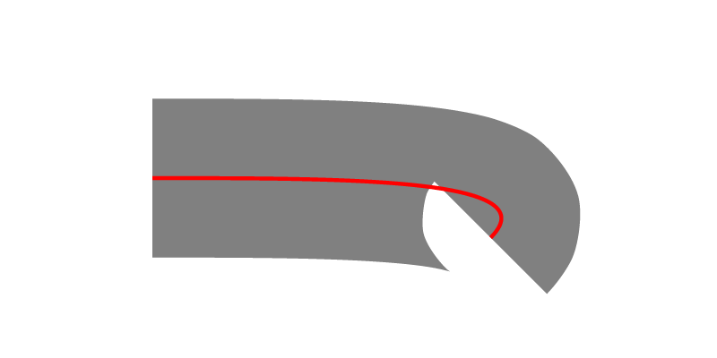
A simple Bezier path segment with high curvature at one end.

A Bezier path segment with high curvature at the end. Web browsers differ on the rendering. (SVG)

Firefox's rendering of the circle. It appears solid. Chome's rendering of the circle. It appears like a donut.

Rendering of above path: Firefox (left/top), Chrome (right/bottom). (PNG)

There are two different ways to stroke a path. The first method is to pass a line segment of length ‘stroke-width’, centered on and perpendicular to the path, from one end to the other. Any pixels the line crosses are part of the stroke. This seems to be what Firefox does. (An equivalent method is to pass a circle of diameter ‘stroke-width’ centered on the path and then clip the semi-circles at the ends.) The second method is to construct two paths, offset by half the ‘stroke-width’ on each side of the original path and then fill the area between the two paths. This seems to be what Chrome does.
A simple Bezier path segment with high curvature at one end.

A Bezier path segment with high curvature at the end. Stroke constructed by offsetting path. Red: original path, blue: offset paths. (SVG)

Rendering engines appear to fall into one of these two camps:
Sweep a line:
Firefox, Adobe Reader
Offset paths:
Chrome, Inkscape (Cairo), Opera (Presto), Evince, Batik, rsvg
The difference can be also be seen in circular paths.
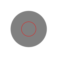
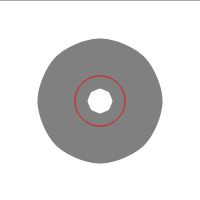
Two circular paths with strokes of different widths.

Two same size circular paths with different stroke widths. When one-half the stroke width exceeds the circle radius (right circle), web browsers differ in their rendering. (SVG)

Firefox's rendering of the circle. It appears solid. Chome's rendering of the circle. It appears like a doughnut.

Rendering of a circular path when one-half the stroke width is greater than the radius in: Firefox (left/top), Chrome (right/bottom). (PNG)

When using the Offset paths method, an inner path is always created. As the direction of this path is the same regardless of the stroke width, one cannot differentiate between the case where the stroke width is less than one-half the radius and the case where it is not. This can be seen in the animation below:
Two circular paths with strokes of different widths. The drawing of the stroke is animated.

Stroking the path. The arrows indicate the direction of the offset paths. If the drawing is not animated, view the image by itself. (SVG)

Interestingly, some renderers draw a filled circle when one-half the ‘stroke-width’ is greater than the radius for an SVG <circle> (i.e. not a circular <path>) while others still draw a doughnut. However, for the SVG <rect> element, the rectangles are always drawn filled if the ‘stroke-width’ is greater than either the ‘width’ or ‘height’ (at least in the renderers I tested). So what does the SVG specification say about how to stroke a path? Nothing…! One can look to PostScript and PDF on which SVG is partially based for a hint on what it should say. The PostScript and PDF specifications say the same thing. From the PDF 1.7 reference:

The S operator paints a line along the current path. The stroked line follows each straight or curved segment in the path, centered on the segment with sides parallel to it. Each of the path’s subpaths is treated separately…

This seems to indicate that the sweeping the line technique is what is expected and indeed, Adobe’s own product, Adobe Reader, appears to do just that.

Stroke Alignment

Designers often want more control over how a stroke is positioned: only on the inside, only on the outside, or some arbitrary ratio of the two. The new SVG ‘stroke-alignment‘ property offers this control. For a closed path, it is relatively easy to figure out how this property should behave:
A figure eight path showing various methods for offsetting.

Top: the original path. Middle: left: stroke inside; right: stroke outside. Bottom: left: stroke to left; right: stroke to right.

For an open path, it is not quite so easy. What is inside, what is outside? One can define the terms by looking at what is filled: inside is in the fill, outside is not in the fill. With this definition, a single straight line segment would render nothing for an ‘inside’ stroke and a stroke on both sides for an ‘outside’ stroke. The SVG specification has a slightly different definition for ‘outside’ (see figure). For an open path it may make more sense to talk about left/right rather than inside/outside.
A figure eight path showing various methods for offsetting.

Top to bottom: Default stroke. Fill area (in gray). Inside (according to SVG specification?). Outside (implemented here by masking). Inside (another interpretation). Outside (according to SVG specification?). Stroke on left (round end cap in pink).

Handling line joins is fairly straight forward. End caps, at least ’round’ ones, are another matter. Does one draw half an end cap? Or does the radius of the end cap match the width of the (shifted) stroke?
Left: straight lines, right: curved lines.

Round end caps. Top to bottom: Default stroke. Stroke alignment ‘outside’, end-cap radius doubled. Stroke alignment ‘outside’, end-cap radius same as normal.

The ‘stroke-alignment’ property was recently removed from the SVG 2 specification draft and moved into a separate SVG Strokes module, partly due to the difficulty in specifying exactly how it should behave. The ‘stroke-alignment’ ‘inside’/’outside’ values can be simulated via other methods. The new ‘paint-order‘ property allows one to paint the stroke before the fill and thus simulating stroking only the outside of the path (this only works for opaque fill). A mask can also be used to simulate stroking the outside of path. A clip path can be used to simulate stroking the inside of a path.

Offset Paths

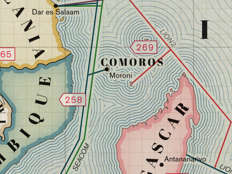
We’ve seen that offsetting a path can be used for constructing strokes. What about offsetting a path for the purpose of creating a new path? This is quite useful in mapping. For example you might want to show multiple bus routes going along a road with different offsets for each route. More stylistically, you could produce the shadowing seen around land masses in older, hand-drawn maps.
Section of map showing lines ringing a group of islands.

An excerpt from a submarine cable map showing the use of offset paths to shade around land masses. Note also the use of inside strokes to define country boundaries.

Offsetting paths is in practice extremely tricky! Here are a few of the problems:
  1. Offsets of Bezier segments are not Beziers; in fact they are 10th-order polynomials. In practice, one can do a pretty good job of estimating the offset by breaking up a Bezier path into smaller segments.
  2. Offset paths can have loops at cusps.
  3. Offset paths may require breaking apart left and right offset paths and recombining to form outset and inset paths. It can be difficult to get this right.
Entire scientific papers are written on this topic.[1] Here is a simple example path with offsets both inside and outside:
Path with a series of offsets.

Left: insets, right: outsets. Red path is original.

In this case, the outsets correspond to the outer edge of a stroked path with appropriate width when the ‘stroke-linejoin’ type is ’round’. The insets correspond to the inner edge of such strokes. Taking a closer look at the offset paths shows a number of cusp loops:
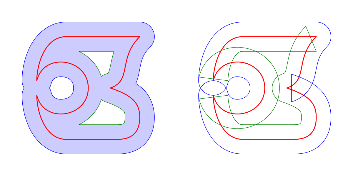
Complex path with offsets.

The same original path as in the above figure. Left: the light blue region is created by stroking the original path. As can be seen it matches the corresponding outset (blue) and inset (green) paths. Right: The raw offset paths used to construct the visible outset and inset paths. In this case, the outset path is constructed from the raw outset path (blue) and the inset path is constructed from the raw inset path (green). Cusp loops and overlaps have been removed.

Determining what is outset or inset becomes more difficult as a path loops back on itself. Both the outset and inset paths can consist of parts of both the right-offset and left-offset paths as shown below:
A path that loops back on itself three times.

Left: The left-offset path (blue) and the right-offset path (green), relative to the path’s direction (clock-wise). Right: The resulting outset path (blue) and inset path (green).

Here’s an example where Inkscape’s Linked Offset function gets it wrong:
A circular path segment on top of a figure eight segment.

The resulting outset path (blue) and inset path (green) as found by Inkscape’s Linked Offset function.

The previous examples assumed that the line joins for outside joins are rounded. It would be desirable to be able to specify the type of join to use. This can maintain the feel of the original path.
A triangle path with 's' shaped sides with various offsets.

Left: Outset path with three different types of joins: ‘bevel’, ’round’, and ‘arcs’. Right: Outset paths with various offsets and with the ‘arcs’ line join. Note: the ‘arcs’ line join fails for the outer most path as the generated arcs do not intersect; this results in falling back to a ‘miter’ line join.

Allowing more freedom to define stroke position and being able to offset strokes are highly desirable features for designers, but as this post shows, they are not so simple to implement. Before we can add such features to SVG, we need to define robust algorithms for generating proper offset paths.

References

  1. An offset algorithm for polyline curves Xu-Zheng Liu, Jun-Hai Yong, Guo-Qin Zheng, Jia-Guang Sun.
An image for the sole purpose of having a good PNG image to show in Google+ which doesn’t support SVG images, bad Google+. Complex path with offsets.

SVG Working Group Meeting Report — Sydney

The SVG Working Group had a four day face-to-face meeting in Sydney this month. The first day was a joint meeting with the CSS Working Group. I would like to thank the Inkscape board for allocating the funds for this trip as well as all the Inkscape donors that made it possible. This was an expensive trip as I was traveling from Paris and Sydney is an expensive city… but I think it was well worth it as the SVG WG (and CSS WG, where appropriate) approved all of my proposals and worked through all of the issues I raised. Unfortunately, due to the high cost of this trip, I have exhausted the budgeted funding from Inkscape for SVG WG travel this year and will probably miss the two other planned meetings, one in Sweden in June and one in Japan in October. We target the Sweden meeting for moving the SVG 2 specification from Working Draft to Candidate Recommendation so it would be especially good to be there. If anyone has ideas for alternative funding, please let me know. Highlights: A summary of selected topics, grouped by day, follows:

Joint CSS and SVG Meeting

Minutes
  • SVG sizing in HTML.

    We spent some time discussing how SVG should be sized in HTML. For corner cases, the browsers disagree on how large an SVG should be displayed. There is going to be a lot work required to get this nailed down.

  • CSS Filter Effects:

    We spent a lot of time going through and resolving the remaining issues in the CSS Filter Effects specification. (This is basically SVG 1.1 filters repackaged for use by HTML with some extra syntax sugar coating.) We then agreed to publish the specification as a Candidate Recommendation.

  • CSS Blending:

    We discussed publishing the CSS Blending specification as a Recommendation, the final step in creating a specification. I raised a point that most of the tests assumed HTML content. It was requested that more SVG specific test be created. (Part of the requirement for Recommendation status is that there be a test suite and that two independently developed renderers pass each test in the suite.)

  • SVG in OpenType, Color Palettes:

    The new OpenType specification allows for multi-colored SVG glyphs. It would be nice to set those colors through CSS. We discussed several methods for doing so and decided on one method. It will be added to the CSS Fonts Level 4 specification.

  • Text Rendering:

    The ‘text-rendering‘ property gives renderers a hint on what speed/precision trade-offs should be made. It was pointed out that the layout of text flowed into a box will change as one zooms in and out on a page in Firefox due to font-hinting, font-size rounding, etc. The Google docs people would like to prevent this. It was decided that the ‘geometricPrecision’ value should require that font-metrics and text-measurement be independent of device resolution and zoom level. (Note: this property is defined in SVG but both Firefox and Chrome support it on HTML content.)

  • Text Properties:

    Text in SVG 2 relies heavily on CSS specifications that are in various states of readiness. I asked the CSS/SVG groups what is the policy for referencing these specs. In particular, SVG 2 needs to reference the CSS Shapes Level 2 specification in order to implement text wrapping inside of SVG shapes. The CSS WG agreed to publish CSS Shapes Level 2 as a Working Draft so we can reference it. We also discussed various technical issues in defining how text wraps around excluded areas and in flowing text into more than one shape.

SVG Day 1

Minutes
  • CamelCase Names

    The SVG WG decided some time ago to avoid new CamelCase names like ‘LinearGradient’ which cause problems with integration in HTML (HTML is case insensitive and CamelCase SVG names must be added by hand to HTML parsers). We went through the list of new CamelCase names in SVG 2 and decided which ones could be changed, weighing arguments for consistency against the desire to not introduce new CamelCase names. It was decided that <meshGradient> should be changed to <mesh>. This was mostly motivated by the ability to use a mesh as a standalone entity (and not only as a paint server). Other changes include: <hatchPath> to <hatchpath>, <solidColor> to <solidcolor>, …

  • Requiring <foreignObject> HTML to be rendered.

    There was a proposal to require any HTML content in a <foreignObject> element to be rendered. I pointed out that not all SVG renderers are HTML renderers (Inkscape as an example). It was decided to have separate conformance classes, one requiring HTML content to be rendered and one not.

  • Requiring Style Sheets Support:

    It was decided to require style sheet support. We discussed what kind of style sheets to require. We decided to require basic style sheet support at the CSS 1 or CSS 2.1 level (that part of the discussion was not minuted).

  • Open Issues:

    We spent considerable time going through the specification chapter by chapter looking at open issues that would block publishing the specification as a Candidate Recommendation. This was a long multi-day process.

SVG Day 2

Minutes

Note: Day 2 and Day 3 minutes are merged.

  • Superpaths:

    Superpaths is the name for the ability to reuse path segment data. This is useful, for example, to define the boundary between two shapes just once, reusing the path segment for both shapes. SVG renderers might be able to exploit this information to provide better anti-aliasing between two shapes knowing they share a common border. The SVG WG endorses this proposal but it probably won’t be ready in time for SVG 2. Instead, it will be developed in a separate Path enhancement module.

  • Line-Join: Miter Clipped:

    It was proposed on the SVG mailing list that there be a new behavior for the miter ‘line-join’ value in regards to the ‘miter-limit’ property. At the moment, if a miter produces a line cap that extends farther than the ‘miter-limit’ value then the miter type is changed to bevel. This causes abrupt jumps when the angle between the joined lines changes such that the miter length crosses over the ‘miter-limit’ value (see demo). A better solution is to clip the line join at the ‘miter-limit’. This is done by some rendering libraries including the one used on Windows. We decided to create a new value for ‘line-join’ with this behavior.

  • Auto-Path Closing:

    The ‘z’ path command closes paths by drawing a line segment to the first point in the path. This is fine if the path is made up of straight lines but becomes problematic if the path is made up of curves. For example, it can cause rendering problems for markers as there will be an extra line segment between the start and end of the path. If the last point is exactly on top of the first point, one can remove this closing line segment but this isn’t always possible, especially if one is using the relative path commands with rounding errors. A more detailed discussion can be found here. We decided to allow a ‘z’ command to fill in missing point data using the first point in the path. For example in: d=”m 100,125 c 0,-75 100,-75 100,0 c 0,75 -100,75 z” the missing point of the second Bezier curve is filled in by the first point in the path.

  • Text on a Shape:

    An Inkscape developer has been working on putting text on a shape by converting shapes to paths while storing the original shape in the <defs> section. It would be much easier if SVG just allowed text on a shape. I proposed that we include this in SVG 2. This is actually quite easy to specify as we have already defined how shapes are converted to paths (needed by markers on shapes and putting dash patterns on shapes). A couple minor points needed to be decided: Do we allow negative path offsets? (Yes) How do we decide which side of a path the text should be put? (A new attribute) The SVG WG approved adding text on a shape to SVG 2.

  • Marker knockouts, mid-markers, etc:

    A number of new marker features still need some work. To facilitate finishing SVG 2 we decided to move them to a separate specification. There is some hesitation to do so as there is fear that once removed from the main SVG specification they will be forgotten about. This will be a trial of how well separating parts of SVG 2 into separates specifications works. The marker knockout feature, very useful for arrowheads is one feature moved into the new specification. On day 3 we approved publishing the new Markers Level 1 specification as a First Public Working Draft.

  • Text properties:

    With our new reliance on CSS for text layout, just what CSS properties should SVG 2 support? We don’t want to necessarily list them all in the SVG 2 specification as the list could change as CSS adds new properties. We decided that we should support all paragraph level properties (‘text-indent’, ‘text-justification’, etc.). We’ll ask the CSS working group to create a definition for CSS paragraph properties that we can then reference.

  • Text ‘dx’, ‘dy’, and ‘rotate’ attributes:

    SVG 1.1 has the properties ‘dx’, ‘dy’, and ‘rotate’ attributes that allow individual glyphs to be shifted and rotated. While not difficult to support on auto-wrapped text (they would be applied after CSS text layout), we decided that they weren’t really needed. They can still be used on SVG 1.1 style text (which is still part of SVG 2).

SVG Day 3

Minutes

Note: Day 3 minutes are at end of Day 2 minutes.

  • Stroking Enhancements:

    As part of trying to push SVG 2 quickly, we decided to move some of the stroking enhancements that still need work into a separate specification. This includes better dashing algorithms (such as controlling dash position at intersections) and variable width strokes. We agreed to the publication of SVG Strokes as a First Public Working Draft.

  • Smoothing in Mesh Gradients:

    Coons-Patch mesh gradients have one problem: the color profile at the boundary between patches is not always smooth. This leads to visible artifacts which are enhanced by Mach Banding. I’ve discussed this in more detail here. I proposed to the SVG WG that we include the option of auto-smoothing meshes using monotonic-bicubic interpolation. (There is an experimental implementation in Inkscape trunk which I demonstrated to the group.) The SVG WG accepted my proposal.

  • Motion Path:

    SVG has the ability to animate a graphical object along a path. This ability is desired for HTML. The SVG and CSS working groups have produced a new specification, Motion Path Module Level 1, for this purpose. We agreed to publish the specification as a First Public Working Draft.

SVG Working Group Meeting Report — London

The SVG Working Group had a four day Face-to-Face meeting just before The Graphical Web conference in Winchester (UK). The meetings were hosted by Mozilla in their London office. Here are some highlights of the meeting:

Day 1

Minutes
  • Symbol and marker placement shorthands:

    Map makers use symbols quite extensively. We decided at a previous meeting to add the ‘refX’ and ‘refY’ attributes (from <marker>) to <symbol> so that symbols can be aligned to a particular point on a map without having to do manual position adjustments. We have since been asked to provide ‘shorthand’ values for ‘refX’ and ‘refY’. I proposed adding ‘left’, ‘center’, and ‘right’ to ‘refX’ (defined as 0%, 50%, and 100%) of the view box as well as ‘top’, ‘center’, and ‘bottom’ to ‘refY’. These values follow those used in the ‘transform-origin’ property. We debated the usefulness and decided to postpone the decision until we had feedback from those using SVG for maps (see Day 4).

    For example, to center a symbol at the moment, one has to subtract off half the width and height from the ‘x’ and ‘y’ attributes of the <use> element:

      <symbol id="MySquare" viewBox="0 0 20 20">
        <rect width="100%" height="100%"
    	  style="fill:none;stroke:black;stroke-width:2px"/>
      </symbol>
      <use x="100" y="100" width="100" height="100"
           xlink:href="#MySquare"/>
    

    By using ‘refX’ and ‘refY’ set to ‘center’, one no longer needs to perform the manual calculations:

      <symbol id="MySquare" viewBox="0 0 20 20"
                      refX="center" refY="center">
        <rect width="100%" height="100%"
    	  style="fill:none;stroke:black;stroke-width:2px"/>
      </symbol>
      <use x="150" y="150" width="100" height="100"
                 xlink:href="#MySquare"/>
    
    A square symbol centered in an SVG.

    An example of a square <symbol> centered inside an SVG.

  • Marker and symbol overflow:

    One common ‘gotcha’ in using hand-written markers and symbols is that by default anything drawn outside the marker or symbol viewport is hidden. People sometimes naively draw a marker or symbol around the origin. Since this is the upper-left corner of the viewport, only one quarter of the marker or symbol is shown. We decided to change the default to not hide the region outside the viewport, however, if this is shown to break too much existing content, the change might be reverted (it is possible that some markers/symbols have hidden content outside the viewport).

  • Two triangle paths with markers on corners. Only one-fourth of each marker on the left path is shown.

    Example of markers drawn around origin point. Left: overflow=’hidden’ (default), right: overflow=”visible’.

  • Variable-stroke width:

    Having the ability to vary stroke width along a path is one of the most requested things for SVG. Inkscape has the Live Path Effect ‘Power Stroke’ extension that does just that. However, getting this into a standard is not a simple process. We must deal with all kinds of special cases. The most difficult part will be to decide how to handle line joins. (See my post from the Tokyo meeting for more details.) As a step towards moving this along, we need to decide how to interpolate between points. One method is to use a Centripital Catmull-Rom function. Johan Engelen quickly added this function as an option to Inkscape’ Power Stroke implementation (which he wrote) for us to test.

Day 2

Minutes
  • Path animations:

    In the context of discussing the possibility of having a canonical path decomposition into Bezier curves (for speed optimization) we briefly discussed allowing animation between paths with different structures. Currently, SVG path animations require the start and end paths to have the same structure (i.e. same types of path segments).

  • Catmull-Rom path segments.

    We had a lengthy discussion on the merits of Catmull-Rom path segments. The main advantage of Catmull-Rom paths is that the path goes through all the specified points (unlike Bezier path segments where the path does not go through the handles). There are some disadvantages… adding a new segment changes the shape of the previous segment, the paths tend not to be particularly pretty, and if one is connecting data points, the curves have the tendency to over/under shoot the data. The majority of the working group supports adding these curves although there is some rather strong dissent. The SVG 2 specification already contains Catmull-Rom paths text.

    After discussing the merits of Catmull-Rom path segments we turned to some technical discussions: what exact form of Catmull-Rom should we use, how should start and end segments be specified, how should Catmull-Rom segments interact with other segment types, how should paths be closed?

    Here is a demo of Catmull-Rom curves.

Day 3

Minutes
  • <tref> decission:

    One problem I see with the working group is that it is dominated by browser interests: Opera, Google (both Blink), Mozilla (Gecko), and Adobe (Blink, Webkit, Gecko). (Apple and Microsoft aren’t actively involved with the group although we did have a Microsoft rep at this meeting.) This leaves those using SVG for other purposes sometimes high and dry. Take the case of <tref>. This element is used in the air-traffic control industry to shadow text so it is visible on the screen over multi-color backgrounds. Admittedly, this is not the best way to do this (the new ‘paint-order’ property is a perfect fit for this) but the fact is that it is being used and flight-control software can’t be changed at a moments notice. Last year there was a discussion on the SVG email list about deprecating <tref> due to some security issues. From reading the thread, it appeared the conclusion was reached that <tref> should be kept around using the same security model that <use> has.

    Deprecating <tref> came up again a few weeks ago and it was decided to remove the feature altogether and not just deprecate it (unfortunately I missed the call). The specification was updated quickly and Blink removed the feature immediately (Firefox had never implemented it… probably due to an oversight). It has reached the point of no-return. It seems that Blink in particular is eager to remove as much cruft as possible… but one person’s cruft is someone else’s essential tool. (<tref> had other uses too, such as allowing localization of Web pages through a server.)

  • Blending on ‘fill’ and ‘stroke':

    We have already decided to allow multiple paint servers (color, gradient, pattern, hatch) on fills and strokes. It has been proposed that blending be allowed. This would follow the model of the ‘background-blend-mode’ property. (Blending is already allowed between various element using the ‘mix-blend-mode’ property’, available in Firefox (nightly), Chrome, and the trunk version of Inkscape.)

  • CSS Layout Properties:

    The SVG attributes: ‘x’, ‘y’, ‘cx’, ‘cy’, ‘r’, ‘rx’, ‘ry’ have been promoted to properties (see SVG Layout Properties). This allows them to be set via CSS. There is an experimental implementation in Webkit (nightly). It also allows them to be animated via CSS animations.

A pink square centered in SVG if attributes supported, nothing otherwise.

A test of support of ‘x’, ‘y’, ‘width’, and ‘height’ as properties. If supported, a pink square will be displayed on the center of the image.

Day 4

Minutes
  • Shared path segments (Superpaths):

    Sharing path segments between paths is quite useful. For example, the boundary between two countries could be given as one sub-path, shared between the paths of the two countries. Not only does this reduce the amount of data needed to describe a map but it also allows the renderer to optimize the aliasing between the regions. There is an example polyfill available.

    We discussed various syntax issues. One requirement is the ability to specify the direction of the inserted path. We settled for directly referencing the sub-path as d=”m 20,20 #subpath …” or d=”m 20,20 -#subpath…”, the latter for when the subpath should be reversed. We also decided that the subpath should be inserted into the path before any other operation takes place. This would nominally exclude having separate properties for each sub-path but it makes implementation easier.

  • Here, MySubpath is shared between two paths:

      <path id="MySubpath" d="m 150,80 c 20,20 -20,120 0,140"/>
      <path d="m 50,220 c -40,-30 -20,-120 10,-140 30,-20 80,-10
                       90,0 #MySubpath c 0,20 -60,30 -100,0 z"
    	style="fill:lightblue" />
      <path d="m 150,80 c 20,-14 30,-20 50,-20 20,0 50,40 50,90
                       0,50 -30,120 -100,70 -#MySubPath z"
    	style="fill:pink" />
    
    This SVG code would render as:
    Two closed paths sharing a common section.

    The two closed paths share a common section.

  • Stroke position:

    An often requested feature is to be able to position a stroke with some percentage inside or outside a path. We were going to punt this to a future edition of SVG but there seems to be quite a demand. The easiest way to implement this is to offset the path and then stroke that (remember, one has to be able to handle dashes, line joins, and end caps). If we can come up with a simple algorithm to offset a stroke we will add this to SVG 2. This is actually a challenging task as an offset of a Bezier curve is not a Bezier… thus some sort of approximation must be used. The Inkscape ‘Path->Linked Offset’ is one example of offsetting. So is the Inkscape Power Stroke Live Path Effect (available in trunk).

  • Symbol and marker placement shorthands, revisited:

    After feedback from mappers, we have decided to include the symbol and marker placement shorthands: ‘left’, ‘center’, ‘right’, ‘top’, and ‘bottom’.

  • Units in path data:

    Currently all path data is in User Units (pixels if untransformed). There is some desire to have the ability to specify a unit in the path data. Personally, I think this is mostly useless, especially as units (cm, mm, inch, etc.) are useless as there is no way to set a preferred pixel to inch ratio (and never will be). The one unit that could be useful is percent. In any case, we will be investigating this further.

Lots of other technical and administrative topics were discussed: improved DOM, embedding SVG in HTML, specification annotations, testing, etc.

The ‘paint-order’ property in SVG 2

Introduction

SVG 2 has a new ‘paint-order’ property which can be used to select the order in which the fill, stroke, and markers are painted. This is of especially great use for text where having the stroke painted on top of the fill leads to distorted glyphs.
Sample text showing effect of paint-order.

Sample text showing the effect of the ‘paint-order’ property.

As of March 2014, Chrome and Firefox Nightly support the ‘paint-order’ property. Inkscape trunk also has rendering support for the property (if compiled in).

Test SVGs

Tests with different orders of 'fill', 'stroke', and 'markers'.

Each square has the indicated value of the ‘paint-order’ property.

Tests with different orders of 'fill', 'stroke', and 'markers'.

Each line of text has the indicated value of the ‘paint-order’ property.

Blending coming to an SVG renderer near you! (Including Inkscape)

SVG has supported a limited set of blend modes through the use of SVG filters. Now SVG (and HTML) are getting a full set of blend modes that can be directly applied to all graphical objects. Chrome already has some support for the new blending method. Here is a snippet of SVG from the specification CSS Blending and Compositing Level 1:
<svg>
  <rect width="120" height="120" fill="black"/>
  <circle cx="40" cy="40" r="40" fill="red"/>
  <circle cx="80" cy="40" r="40" fill="lime"/>
  <circle cx="60" cy="80" r="40" fill="blue"/>
</svg>
Normally, SVG uses the painter’s model where each element is painted on top of the previous. So the above SVG gets rendered as (actual inline SVG):

Inlined SVG. Circles drawn using painter’s model.

With CSS blending, one can specify how the blending between the elements is done by setting the ‘mix-blend-mode’ property. The following style rule: circle { mix-blend-mode: screen; } yields the following figure:

Inlined SVG. Circles blended with ‘mix-blend-mode’ = ‘screen’.

which in a browser (recent Chrome) that supports CSS blending should look like this:
Red, lime, and blue overlapping circles, blended with 'screen' mode.

PNG.

Why the black background? If the background was white, the circles would not be visible. This is because the circles blend not only with each other but also with the background. (With the ‘screen’ blending mode, any color blended with a white background results in white.) To stop blending with the background, one can use the ‘isolation’ property. By wrapping the three circles in a group and setting the ‘isolation’ property to ‘isolate’, the three circles are first blended onto a transparent, black background and then the resulting image is painted normally. The code looks like this:
<svg>
  <g>
    <circle cx="40" cy="40" r="40" fill="red"/>
    <circle cx="80" cy="40" r="40" fill="lime"/>
    <circle cx="60" cy="80" r="40" fill="blue"/>
  </g>
</svg>
and the CSS: circle { mix-blend-mode: screen; } g { isolation: isolate; } The resulting image should look like this:
Red, green, and blue overlapping circles, blended with 'screen' mode.

PNG.

I wasn’t able to get the ‘isolation’ property to work with Chrome (which should support it), thus I used a PNG in the above figure. At the SVG Working Group meeting last week, the group approved moving the CSS Compositing and Blending Level 1 to a Candidate Recommendation. Since this a joint specification, the CSS Working group must also give their approval. A Candidate Recommendation is the last step before becoming a Recommendation (i.e. an official W3C specification). During this last step two things must happen. First a comprehensive test suite must be written and second at least two different implementations must pass the tests for each feature in the specification. This latter requirement ensures that the specification is clear enough that it can be implemented (and also demonstrates there is a real interest in the specification). Chrome already implements the specification so just one more implementation is needed. It is expected that Firefox will soon support the specification. There is also a test plan that includes SVG tests. So we are well on the way to getting this through the last step. In addition, I’ve also just added support for CSS Blending to Inscape trunk. For the moment, a compile time flag must be set to enable the support. There is no GUI (other than the XML editor) and there is still a bit of work to be done (the Inkscape canvas background needs to be isolated from the drawing and I’ve seen a bug when part of the drawing is cached. The CSS Compositing and Blending Level 1 specification also include a full set of Porter-Duff compositing operators. For the moment, they only apply to Canvas. It was intended that they apply to HTML and SVG but the rendering models used by browsers cannot yet accomodate them. They will be included in the next version of the specification, CSS Compositing and Blending Level 2. The SVG working group approved the start on the next level at the last meeting. Blending and compositing has been included in SVG filters from the beginning. However, only a limited set of blending modes and compositing operators are available in SVG filters. Unfortunately, CSS Filters Level 1 has not extended filters to include the new blending modes and compositing operators despite being trivial to implement once the original set has been implemented (it took me all of an hour to add them to Inkscape trunk). Again the motivation is to speed up approval of the level 1 specification; level 2 will include them. Work on level 2 is expected to begin early next year. If you are interested in playing with then new blending modes and compositing modes in Inkscape, check out Inkscape trunk and set the flags WITH_CSSBLEND and/or WITH_CSSCOMPOSITE (see the file configure.ac). As mentioned above, there is no GUI for the new non-filter based blending modes. The new blending modes and compositing operators for filters are available through the Filters dialog. You can also have a look at my Blending Test Page.

SVG Working Group Meeting Report — Tokyo

The SVG Working Group had a three day Face-to-Face meeting in Tokyo at the beginning of June. The first two days (hosted by Mozilla) were devoted to SVG proper while the third day (hosted by Google) was a joint meeting with the CSS Working Group. As typical, a lot of time was devoted to nitty-gritty details that only browser coders could love but there were still plenty of things of interest for artists and their brethren:
  • Wrapped text: I presented a proposal based on using the CSS Exclusions and CSS Shapes specifications. As I wrote earlier, the current Level 1 version of these specifications are missing the exact features we need, namely “shape-inside” (to provide a wrapping context) and references to SVG elements; both were recently removed. However, when we met with the CSS working group we were told that they would be back in the Level 2 specs. Alan Stearns promised to get the Level 2 drafts out soon so we have something to reference.

    Doug Schepers presented his idea on a simple way to provide a rectangular wrapping context which would not require CSS Exclusions or CSS Shapes:

     <text x="20" y="30" width="200"
        font-size="20px"
        alignment-baseline="top">This text wraps at 200 pixels.<text>
    
    Horizontally wrapped text inside box 200 px wide.

    Horizontally wrapped text.

    Or for vertical text:
     <text x="20" y="30" height="200"
        font-size="20px"
        alignment-baseline="text-before-edge">テキストは
           10文字の後に折り返されます。<text>
    
    Vertically wrapped text inside box 200 px high.

    Vertically wrapped text.

    Specifying only the “width” or the “height” creates an infinitely long rectangle for wrapping text. Specifying both creates a finite rectangle. The visibility of text that overflows this finite rectangle is controlled by the overflow property. One small problem with Doug’s proposal is that the values of “x” and “y” normally refer to the baseline of the first line of text and not the upper left corner of the rectangle wrapping area. This can be changed by specifying the “alignment-baseline” property to top or text-before-edge. Note that Doug’s proposal and my proposal are not mutually exclusive and we will mostly like incorporate both. Both the SVG and CSS working groups are amenable to the proposals. There are some details to work out. For example, in my initial proposal one would specify that text should flow sequentially into two different objects by giving a comma separated list: shape-inside=”url(#shape1), url(#shape2)”. This, I am told, won’t work as in CSS it indicates that the text should flow into the two shapes as if they were one shape. Instead, it has been suggested that either CSS Regions and/or CSS Fragments be used. This, however, seems overly complex.

  • Variable width stroke: We discussed various aspects of variable width strokes. It is clear that it will take some work to come up with a good specification. Problems include: how to specify positions, widths, smoothing, line joins, and end caps. Whether or not this gets into SVG 2 will depend on how fast these issues are resolved and in the timing of SVG 2. It it doesn’t get into SVG 2, it certainly will get into the next version. For example, here are some possible ways of drawing a “round” stroke-linejoin:

    Possible ways to draw a “round” stroke-linejoin when there is a discontinuity in line width at a corner node. Top: using a “pen” with diameter of the smallest width. Bottom: using an ellipse.

    Circles and ellipses work well when the two line segments intersect at 90 degrees. At other angles or when the line widths are changing they aren’t as useful. Here is an attempt at using a Bezier with a handle length chosen so that it matches a “round” stroke-linejoin when the width is constant.

    Possible way to draw a “round” stroke-linejoin: using a Bezier curve. The handle length is calculated so that it reduces to a circular arc when the width is constant (length is 0.552 × angle between tangents in degrees / 90 × distance from end to intersection of tangents). The handles are shown in purple.

    Here is a challenge: Come up with a method that produces a suitable “round” stroke-linejoin in each of the following cases:
    Figures with various angles between the two path sections.

    A triangle shape is applied to a path with two sections. The angle between the two sections is changed from figure to figure. How would you construct a “round” stroke-linejoin between the two sections that works in all cases?

  • Marker rendering issues: SVG renderers differ on how markers are rendered for corner cases such as a polyline with one point (see: http://paullebeau.com/svg2/markers/). We sorted out the details. As part of the discussion, we agreed that markers should apply to rectangles, ellipses, and circles (and in the future stars). The basic rule, is that markers are drawn as if these shapes were rendered as paths. We explicitly decided that circles and ellipses would have four markers.
    Marks shown on a rectangle, rounded rectangle, circle, and ellipse.

    Markers drawn on various shapes.

  • New value for the marker property orient: “auto-start-reverse”: This value indicates that a marker should be reversed if it is at the start of a path. This is so that one needs to define only one marker (like an arrowhead) and use it both as a start and an end marker (like a double-headed arrow). This has already been added to the spec and is in the process of being implemented in Firefox.
      <defs>
       <marker id="MyArrowHead"
          viewBox="0 0 10 10" refX="0" refY="5" 
          markerUnits="strokeWidth"
          markerWidth="4" markerHeight="3"
          orient="auto-start-reverse"
          fill="black">
          <path d="M 0 0 L 10 5 L 0 10 z" />
        </marker>
      </defs>
      <path marker-start="url(#MyArrowHead)"
            marker-end="url(#MyArrowHead)"
           d="m 75,75 150,0" />
    
    Double headed arrow using auto-start-reverse.

    Path with just one defined marker using orient=”auto-start-reverse”.

  • Hatch patterns: I recently added hatch patterns to the SVG 2 specification. The work was approved with a few small changes (renaming a property and specifying that only solid colors can be used… no hatches inside hatches!).
  • Multiple fill and stroke properties: As part of our discussion of hatch patterns, we discussed the ability to specify multiple fill and stroke properties. This is useful, for example, to draw a hatch over a gradient fill, or in drawing cross-hatching. We agreed to how this would be specified. This is a first step to allowing things like multiple stroke widths and colors on paths but at the moment there is some resistance to handling these more complicated cases. The feeling is that we need to start limiting what is being added to SVG 2 so that we can get it finished.
      <defs>
       <hatch id="MyHatch1" ... >
       <hatch id="MyHatch2" ... >
      </defs>
      <rect x="50" y="50" width="200" height="200"
         fill="url(#MyHatch1),url(#MyHatch2),#a0a0ff"</rect>
    
    A simple cross hatch over a light blue fill.

    A multiple fill consisting of two hatch patterns over a solid light blue fill”.

  • Filter compositing: feBlend: As anybody who has used the feBlend filter primitive to blend an element with transparency with a background image knows that the background gets added twice, once with the blending and once when the blend result is composited with the background. (See my example.) We can’t change the behavior of feBlend as there is too much content out there that uses it. We did agree to add a new attribute that will allow turning off compositing.